Many machinists put their backs at risk because they have no good way of easily and quickly moving heavy machining fixtures from storage into CNC/NC machines, or putting these machining fixtures back into storage. A large number of machine shops have devices capable of lifting and moving very heavy objects but they are usually large, unwieldy, and not cantilevered out to reach into optimal places. Currently a smaller and more practical machine shop lifting device tailored to CNC machines does not exist in the marketplace. Without further relevant data it is hard to comment quantitatively on the need that exists within machine shops, but qualitatively there is definitely a product opportunity gap here. Back health is a huge issue that makes this problem extremely real for machinists all around America. If our solution combats this problem, combined with the fact that there doesn't seem to be anything equivalent in the marketplace, we could have a viable product to build a business around.
Our practical CNC fixture lifting device would be desired by anyone working with CNC or NC machines in danger of damage to their back. In the U.S., the machine shop industry includes about 20,000 companies with a combined annual revenue of about $40 billion. These machine shops don't even include all the various situations where users may need help lifting and moving heavy fixtures. With this in mind we can conclude that our target market for our lifting device is more than sufficient to base a successful business on.
In terms of our specific project goals, we wish to provide Robert Sjostrom, our "customer", with a fully functional prototype by the end of the semester that can easily lift and move heavy CNC machining fixtures. A previous senior design team attempted to make a mechanical lifting device, but ours will be a complete redesign starting at the customer. We want to enable the user to easily lift and place large machining fixtures into and out of CNC machines and move these fixtures to storage. After fully understanding customer requirements, we will design the prototype, and with the help of Dave Brigham from Raymond Corporation we will build a working prototype.
Directly below is our design process leading up to our first detailed designs.
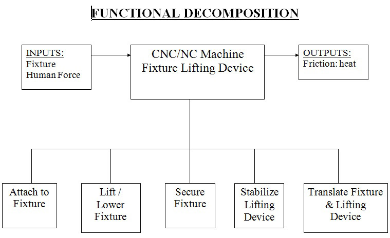
Our starting point, breaking down the inputs and outputs to our lifting device, and all the actions that our machine will have to be responsible for accomplishing.

The chart outlines all the solutions we generated to accomplish the tasks listed above in the Functional Decomposition. We then used weighted Pugh Charts to help us choose which solutions and systems of solutions made the most sense.

A quick artists' sketch of what our combined solutions might look like. The idea is that the winch which picks up the fixture is attached to a trolley which is capable of moving in and out of the envelope of the CNC machine. Thus after the fixture is picked up, the user simply slides the trolley back so the fixture can best let down onto the rest table within the envelope of our machine. This prevents the fixture from swinging around while transporting it, and also highly reduces the chance of the device tipping over which was a problem with past versions.

A quick sketch of how we plan on getting the trolley to move back and forth.
With our preliminary design phase finished, we all agreed to make a machine that was capable of picking up the fixture, sliding the fixture within the envelope of the machine so that the lifting machine was stable, and making the fixture stationary during transport so that it was not oscillating back and forth. We would achieve this by having a central "trolley" with the winch on it (and a means for braking) that could slide into the envelope of the CNC machine, and then slide back into the envelope of our machine. The trolley would slide back and forth on bearings sitting in a U-shaped channel for fluid motion. We would have a table at the front of our lifting device that the fixture could be set down onto during transit so it would not oscillate at the end of the winch cable. And finally, we would have heavy weights at the back of the lifting device so the cantilivered trolley would not tip over while picking up a 200 lb. fixture. Our detailed designs that reflect our core decisions are pictured belown as renderings.
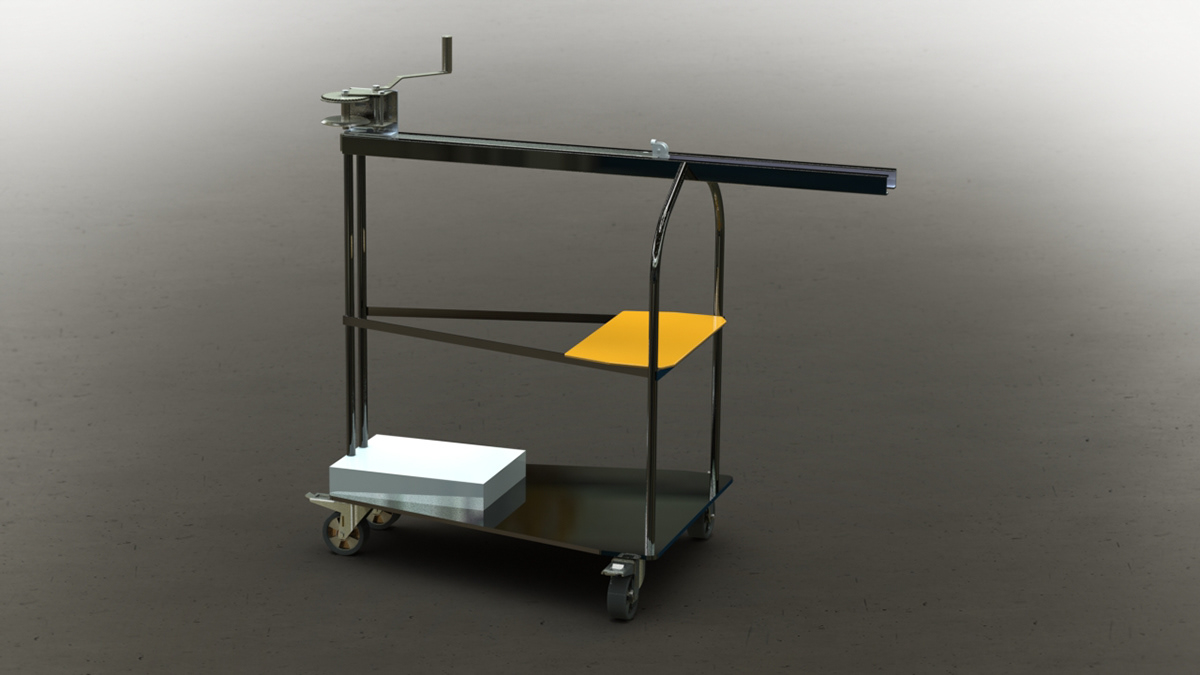
A rendering of our initial conceptual design made within Solidworks.
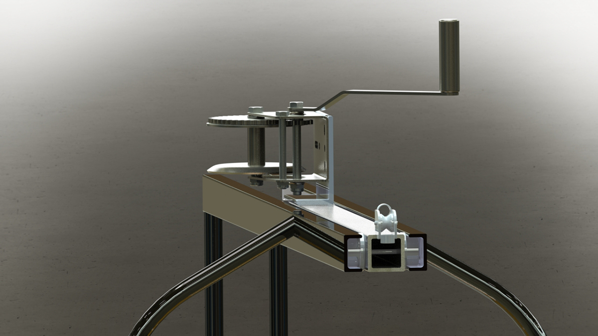
A closeup of the trolley which rolls on bearings in and out of the envelope of the CNC machine to pick up the fixture.

The lifting device being used with a CNC machine.

At this point this is part of a more detailed design. The bearings fit inside the U-channel to allow the square tube stock "trolley" to roll freely, while the toggle clamp allows the user to brake the trolley from moving during lifting sequences.

A cutaway view of where the end of the trolley will be during the fixture lifting process.
After starting the building phase and acquiring our U-channel, we realized that the U-channel's dimensions were very different from what we expected. The profile shape of the U-channel was actually closer to a "W" shape, as pictured directly below. We decided that it would be best to insert a square shaped profile channel into the larger U-channel for the bearings to roll on. We also quickly realized that it would be best for the Winch to be mounted flat on top of the trolley along with the trolley brake, as it turned out we had plenty of clearance with the winch handle. I also managed to weld together pieces from a fence pole digger machine we had access to for the winch cable roller guide at the end of the trolley. All of these design revisions are reflected in the renderings below, and after these we see the final completed trolley system.


Drilling the holes for all our mounting points. The two aluminum blocks pinch tightly around our bearing shafts and are responsible for affixing the shaft rigidly to the trolley beam. Our winch brakes in both directions but can turn in both directions, and on the left is our clamp brake.

The winch cable guide roller I welded together.

Installing the retaining rings and bearings on the bearing shaft so the trolley beam can roll smoothly on the inner raceway rail.

Machined sliding block made of white UHMW that make contact with the inner raceway to provide a smooth sliding motion.

After bolting the inner raceway to the outer U-channel beam, we needed to shim the remaining clearance space with sheet metal.

The complete trolley beam assembly with a very solid handle at a 45 degree angle so the user can easily move the trolley back and forth.

The final trolley system. The trolley slides so smoothly and effortlessly it is an extremely gratifying feeling. With somebody holding down the rear, we have lifted heavy objects in test scenarios successfully.
After finishing the assembly of the trolley system, we had to start designing the support structure.We didn't have much time left so we decided to get rid of our welded steel frame in favor of 8020 extruded aluminum. The concept of the frame remains the same, where we have the counterweights in the back, and a table in front which the fixture rest on during transfer. Below are our final renderings of the lifting unit with the 8020 support structure. Unfortunately 8020 isn't very cheap, so we approached Joe Estano to purchase our required parts on behalf of BU's EPIC Studio, but he refused because this project might just get reassigned next semester. We wanted a fully functional prototype, and eventhough we had the trolley finished which embeds the core functionality of our lifting device, we wanted more. Thus we decided to build the support structure out of wood, so we could at least express the true functionality of our hard work.


Below are pictures of our team developing our functional prototype made out of wood. We had to make the structure extra strong to account for the change in material. We enjoyed working with material that was so much easier to cut compared to metal, but we quickly realized that 2x4's are not straight....especially when you have to carry them back from the hardware store in the rain. However, using shims and a nice chop saw, we were able to make all key dimensions to specification. After completion, I spent a few days spray painting our creation and then we reassembled the top trolley. We tested our lifting device and it worked great! Our customer Bob was extremely happy with the end result.


