Team Members: Lennart Bochmann, Colin Hurlbut, WooJung Choi, and Abhishek Khemka
Advised by: Moneer Helu and David Dornfeld, UC Berkeley
About the Project:
This is a project that I worked on while taking the course ME 220: Precision Manufacturing. This course provides an introduction to fundamental concepts of precision engineering for manufacturing applications. The work completed in ME 220 and as part of Mr. Bochmann's Masters thesis was combined and included in the proceedings of the American Society for Precision Engineering Spring Topical Meeting. This work was further refined and accepted as a journal publication to a special issue of Surface Topography: Metrology and Properties.
Publications:
* C. Bayley, L. Bochmann, C. Hurlbut, et al. “Understanding Error Generation in Fused Deposition Modeling”
Proceedings of the American Society for Precision Engineering Spring Topical Meeting
April 2014
* L. Bochmann, C. Bayley, M. Helu, R. Transchel, K. Wegener, D. Dornfeld, “Understanding error generation in fused deposition modeling”
Surf. Topogr.: Metrol. Prop. 3 (2015) 014002
January 2015

Research Objectives:
Our objectives in working on this project evolved over time and included:
* Determining sources of imprecision in Fused Deposition Modeling (FDM)
* Performing a part quality analysis of a control part by varying parameters
* Characterizing performance metrics for Dimension BST 1200 & Dimension SST 1200 FDM machines to identify sources of error in the printed control part.
Methods:
We designed a control part and six identical test pieces were manufactured on two FDM machines: Stratasys Dimension BST 1200es and SST 1200es. The parts were produced with two different density settings from each machine: solid and sparse-low density. All other parameters were kept constant. Part quality was assessed by measuring surface roughness, dimensional accuracy, & form completion.


Process of Producing the Control Parts:

Observed Errors:

In this image, you can see that the edges of the cube features are not completely flat.
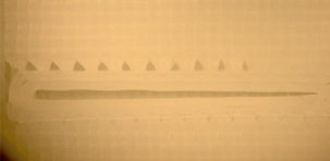
Form error observed in the control part. Above the tear drop feature are holes where material was not deposited.
Measurements:
An Olympus SZ optical microscope was used to measure the form and resolution of the control part. Form was evaluated using the measured roundness of the hemisphere feature, as well as qualitative observations. Resolution was estimated from the length and minimum width of the tear drop feature.
Surface roughness was also measured, given the measurement the directions shown below. These measurements were conducted at Lawrence Berkeley National Lab using a MarSurf M1 stylus-tip profilometer.

Measurement directions for determining the surface roughness of the control part.
Findings: Form & Resolution

Acknowlegments
We would like to Scott McCormick and Gordon Long of the ME Student Machine Shop for their valuable assistance and guidance with this research.
For more detailed information about this project, we encourage you to review the two publications. Below is the abstract for the journal article.
L. Bochmann, C. Bayley, M. Helu, R. Transchel, K. Wegener, D. Dornfeld, “Understanding error generation in fused deposition modeling”
Surf. Topogr.: Metrol. Prop. 3 (2015) 014002
January 2015
Surf. Topogr.: Metrol. Prop. 3 (2015) 014002
January 2015
Abstract
Additive manufacturing offers completely new possibilities for the manufacturing of parts. The advantages of flexibility and convenience of additive manufacturing have had a significant impact on many industries, and optimizing part quality is crucial for expanding its utilization. This research aims to determine the sources of imprecision in fused deposition modeling (FDM). Process errors in terms of surface quality, accuracy and precision are identified and quantified, and an error-budget approach is used to characterize errors of the machine tool. It was determined that accuracy and precision in the y direction (0.08–0.30 mm) are generally greater than in the x direction (0.12–0.62 mm) and the z direction (0.21–0.57 mm). Furthermore, accuracy and precision tend to decrease at increasing axis positions. The results of this work can be used to identify possible process improvements in the design and control of FDM technology.
Additive manufacturing offers completely new possibilities for the manufacturing of parts. The advantages of flexibility and convenience of additive manufacturing have had a significant impact on many industries, and optimizing part quality is crucial for expanding its utilization. This research aims to determine the sources of imprecision in fused deposition modeling (FDM). Process errors in terms of surface quality, accuracy and precision are identified and quantified, and an error-budget approach is used to characterize errors of the machine tool. It was determined that accuracy and precision in the y direction (0.08–0.30 mm) are generally greater than in the x direction (0.12–0.62 mm) and the z direction (0.21–0.57 mm). Furthermore, accuracy and precision tend to decrease at increasing axis positions. The results of this work can be used to identify possible process improvements in the design and control of FDM technology.