Introduction:
Hi all,
I have decided to share/publish some of the top-level design of my current biggest R&D project.
I am developing it on my spare time for my own interest.
I especially like this project because it involves almost all the fields I am interested in:
1. Electro-Mechanical System-Design.
2. Physical modeling & control-loop design.
3. Real-time programming.
4. Embedded electronics.
5. Communication.
6. And some RC-model skills and understanding :-)
The project started as an idea I'd had for a long time. I've been watching on YouTube and such, some inspiring videos of creative and talented people trying and achieving the same goal as mine. In the passing few years I've gained experience in almost all fields needed in such a project. On 2010 I felt that I passed the "critical knowledge barrier" and could start a design of my own.
In the following presentation I will not go into low level design explanations, algorithm or mathematics I used, but just give a general view of all the development stages I passed so far.
In the following presentation I will not go into low level design explanations, algorithm or mathematics I used, but just give a general view of all the development stages I passed so far.
Step 1:
I designed a real-time simulation in order to test the feasibility and the theoretical basis of my model.
My simulation was based on:
1. Theoretical literature research on 3D-transforms, system-control and Aerodynamics.
1. Experimental data collected on motor + propeller (i.e: trust, torque, RPM vs input current; measurements were done using a device especially designed, by me, for this purpose).
2. Estimated weight and dimension.
The above video shows an early version of a real-time simulation done in Simulink and VRML.
Its gives a sense of feeling how the angle control loops stabelize the craft. I am actualy flying the craft with
the joysticks. The stick position sets the rate of rotation in every axis. The simulation simulates the motor
+ propeller thrust and torque, MEMS sensors response, body inertia and basic control loops.
The above video shows a later version of a real-time simulation done in Matlab\Simulink and VRML.
Its gives a sense of feeling how a second layer of velocity control loops ease the flight control of the craft.
Later, I understood that this is not practical with standard GPS due to the noise and accuracy.
Its gives a sense of feeling how a second layer of velocity control loops ease the flight control of the craft.
Later, I understood that this is not practical with standard GPS due to the noise and accuracy.
That conclusion drove me to learn about sensor-fusion and Kalman-filter theory.
Step 2 - Infrastructure:
Almost the entire system is build with ready-made IP I had from previous work I done in different fields:
1. The communication protocol and RF link is from my garden automated irrigation system.
It is design according to the 7-layers model, but with 4-layers only ( 1,2,3,7). This modular design made it possible to easily change the physical-layer without doing entire protocol redesign. The crafts internal LAN run over RS485 phy and the wireless link is done over IEEE802.15.4 phy by a special bridge/access-point-unit I designed. Using the same network for everything in the project made it easy for me to monitor and control all units in real-time and without extra complexity of adding hardware "hooking", extra code or hardware.
2. The controllers (Smart-Samplers PIC18F version) are the same ones I am using in all my projects.
http://www.behance.net/gallery/SmartSampler-V2/1215895
They have a special RTOS I designed and enhanced over the years. They also include the protocol stack I am using. Each Smart-Sampler unit can run one user-application. This is important because by doing so I avoid using a unique firmware-version for each one of the units in the system. In addition to that, the user-application can be programmed and debugged remotely over the network which makes it very easy to integrate and maintain (especially when the system is free to move around).
3. In order to keep my simulation & mathematical model as real as possible, I had to model the propeller + motor configuration. For that purpose I made (with the help of my father) a testing platform for propellers and motors.
The platform measure the following parameters (in static air):
-Propeller Thrust [N]
-Propeller Torque [Nm]
-Propeller RPM
-Motor Current
-Motor Voltage
With these parameters interesting plots can be made that describes the prop + motor performance e.g:
The platform measure the following parameters (in static air):
-Propeller Thrust [N]
-Propeller Torque [Nm]
-Propeller RPM
-Motor Current
-Motor Voltage
With these parameters interesting plots can be made that describes the prop + motor performance e.g:

4. The IMU:
For that purpose I used the same MEMS sensors I am already familiar with and own.
The calibration process is done using computer controlled environmental-test-oven and computer controlled stepper-motor with proper mechanical JIG (I had to calibrate 3-axes x 3-sensors).
The environmental-test-oven is small and quite TEC based 0 to 85Cdeg, which I also designed and build for this type of operations)

The TEC based environmental test oven 21x21x30[cm] 6Kg
One stage of a 6DoF-IMU calibration procedure - +Y axis @50Cdeg, 0.785[Rad/Sec].
The 1DoF Gimbal and Test-Oven are fully controlled by the PC running the calibration procedure.
The calibration mathematics was developed under Mathcad and then rewritten in awk.
Currently each axis of the IMU is automatically calibrated without user intervention.
I am thinking to make a simple 6DoF Gimbal which will make the calibration procedure completely autonomous.
I will probably use my 3D-Printer to make most of its parts.
For more information you are invited to visit my project page in the following link:
http://bit.ly/xspVKi

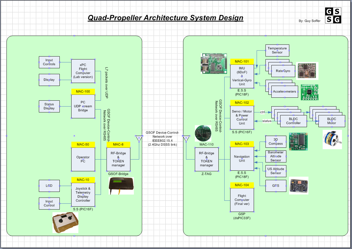
Step 3 - System Architecture:
I divided the system to the following subsystems:
1. Motor & Power-Distribution Unit (PDU) - It main tasks is as follow:
Power-Distribution-Unit:
a. Deliver the power from the battery to the BLDC-speed-controllers
b. Has x4 digitally controlled SSR (one for each motor)
c. Has x4 fuses, x4 current sensors
The SSR control-signal are mapped as an I/O register for remote & local access.
The current sensor can be read manually or be configured to automatically broadcast its measurements.
Motor-Controller:
a. 4x PW generator for the BLDC-speed-controllers
b. 4x Frequency counters to measure the RPM of every motor.
c. 4x Temperature sensors (one for each motor)
The motor controller is managing x4 state-machines that monitor and control the BLDC-motors.
The states are OFF, START & WORKING. The controller can recognize a motor fault and immediately restart it
The temperature, RPM and state can be manually read or configured for automatically broadcast
The unit also calculate an emphasis algorithm to enhance the step response of the motor.
2. IMU and AHRS Unit:
a. 6DoF IMU with 3D magnetic compass and barometer. Runs sensors fusion algorithm to find Euler-Angles.
The IMU is used for measuring the inertial sensors and output calibrated physical data.
The AHRS runs sensors fusion algorithm, over the IMU data, to find the current craft angular state.
In the future the algorithm will do sensor fusion between the GPS & AHRS + INS to provide high accuracy and high rate of position & velocity measurement.
3. Flight Computer - Perform all the hard-real-time operations (like control loops) in order to perform a stabilize maneuvers according to the operators or Navigation-Unit command.
4. Navigation Unit:
a. Standard GPS.
b. Ultrasonic range meter (for low altitude hovering)
c. Barometer for high altitude flight
The Navigation Unit will calculate the flight path by using PVT table.
It is the most high-level unit in the system. It acks as the pilot and it is communicating directly with the flight computer.
As I explained before, the entire system uses the same network.
Step 4 - First Integration
4.1 Lego Based Assembly
Testing the UDP to RS485 bridge and RF datalink channel
1st version of a simple 9DoF IMU:
3x Accelerators
3x Gyros
2x Magnetometers
1x Barometer

I decided to use Tech-Lego blocks for the preliminary design. The entire chasis and 3DOF test-fixture were build with standard Lego blocks & old HDD body. The entire setup took 2 days to design and build and cost me nothing because no mechanical design, manufacture and material were needed.
In the first two weeks I made 3 chassis changes - It was very fast and easy to perform them.
In the first weeks the system was unstable in a very violent way. Only after 3 long weeks I finally had a relatively stable setup. It seems that the Quad stability is much more sensitive to digital delays (Latency) then I anticipated. Some of the things I learned and implemented are:
1. Latency is not a linear function. Hence I had to linearize it in order to add it in my mathematical model. But it is clear that with the current system BW the only practical solution is to minimize the delay to around 20mS.
2. Regular ESC has some kind of input FIR LPF that add around 0.1Sec delay between the input to output (When using ~50hz control signal).
Luckily, It can be reduced by over-driving it with 400hz signal. I will also add a special manipulation on the input signal that also compensates for the inertia delay of the motor.
Luckily, It can be reduced by over-driving it with 400hz signal. I will also add a special manipulation on the input signal that also compensates for the inertia delay of the motor.
2. The control algorithm should output it result in the current time step and not the next one (No pipe line calculation allowed)
3. I had to enhanced the respond time of the UDP to RS485 bridge and lower it from ~50ms to ~2ms.
4. Some of the control-loops include prediction algorithm, on the feedback channel, in order to over come the remaining delay.
Only After understanding and implemented the above The Quad started to show signs of stability and sanity.
The New and Improved Aluminum Based Chasis
4.2 Aluminum Based Chasis
The Lego design took me a long way and it proved to be very time and cost efficient setup for training and evaluation.
But I learned that the chassis should be bigger and stiffer for the current motors & propellers I use.
The design and assembly of the new setup (Quad & 4DOF test-fixture) took me 1 week. It proved to be much more stable.
The dimension between motors is 60cm and total weight is ~700g. It consumes ~280w (12v/22A) when hovering. The weight can be reduced by using shorter & smaller aluminum profiles.
My conclusion from the tests where as follow:
1. I should start the design of the on board Flight-Computer. Doing so will result in more reliable system and with a wider BW of ~100Hz..
2. Change the motors to low RPM/V (~750RPM/V) - I feel the my current 1500KV motors are too sensitive and have relative long mechanical delay (inertia delay)
1. I should start the design of the on board Flight-Computer. Doing so will result in more reliable system and with a wider BW of ~100Hz..
2. Change the motors to low RPM/V (~750RPM/V) - I feel the my current 1500KV motors are too sensitive and have relative long mechanical delay (inertia delay)
This is an important step toward the testing of the Quadee without the test-fixture.
The New and Improved Electronics (using dsPIC30F)
3rd generation of IMU / AHRS:
This version also has Inertial-VSI and altimeter with ~0.2m accuracy.
The firmware of this AHRS was developed with modular concept:
1. My standard RTOS with special drivers for each peripheral of the dsPIC
2. My standard communications stack
3. The AHRS algorithm was developed under Matlab/Simulink in RealTime-Window-Target and then automatic code generated as a new task under the RTOS.
This way I can easily migrate to different type of MEMs sensors and continue to develop the AHRS algorithm with ease under Matlab/Simulink
Same concept for the Flight-Control-Unit (FCU) but two approaches:
Option A:
1. Develop an entire new separate electrical board
2. Use my standard RTOS + communication stack.
3. Develop the FCU algorithm under Matlab/Simulink in RealTime-Window-Target and then automatic generate the code as a new task under the RTOS.
1. Develop an entire new separate electrical board
2. Use my standard RTOS + communication stack.
3. Develop the FCU algorithm under Matlab/Simulink in RealTime-Window-Target and then automatic generate the code as a new task under the RTOS.
Option B:
1. Use the current AHRS electronics.
2. Develop the FCU algorithm under Matlab/Simulink in RealTime-Window-Target and then automatic code generated as a new task under the RTOS.
1. Use the current AHRS electronics.
2. Develop the FCU algorithm under Matlab/Simulink in RealTime-Window-Target and then automatic code generated as a new task under the RTOS.
I think to go with option B and push the dsPIC to it limits (I have extra 40Mhz to waste :-) )

Old vs new mechanical differences:
In the old version the IMU is located on top - Not a good concept because the vibrations are getting stronger farther from the C.G

In the new version - the IMU is closer to the C.G.
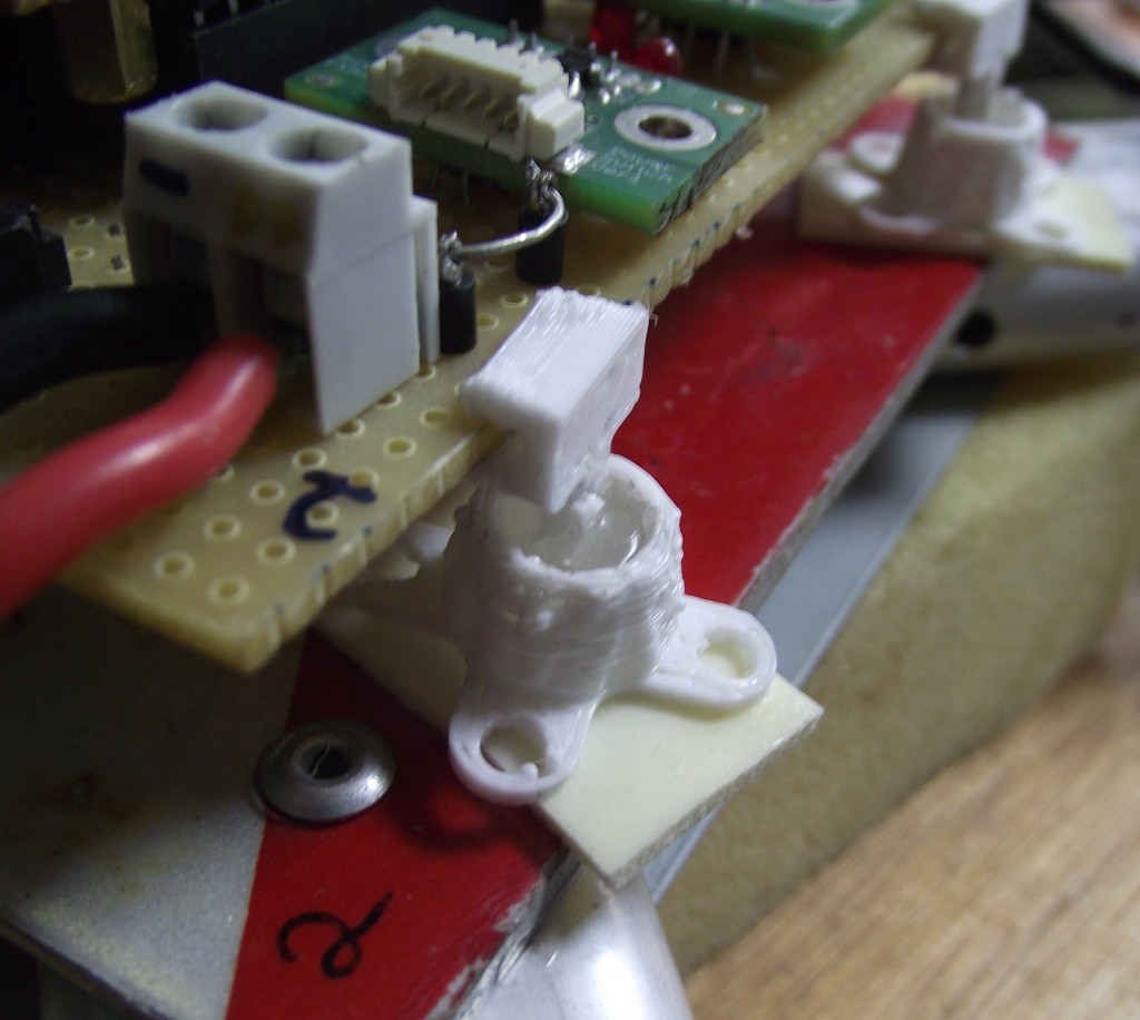
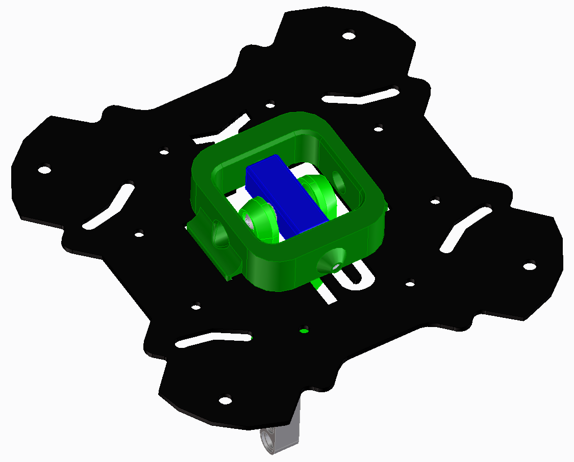
The entire board-stack has better vibration isolation by using a silicon based dumpers (which I designed in PTC-CreoElement and printed in my Huxley 3D-Printer).
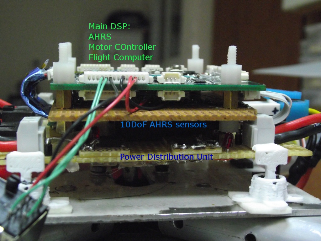
The new setup is better then the old one but it didn't delivered the performance leap I was hoping to get.
I measured that it takes ~250ms for the motor to reach ~90% of the needed RPM.
I measured that it takes ~250ms for the motor to reach ~90% of the needed RPM.
I am currently developing a close-loop RPM controller for each motor. I am hoping to improve the step-respond of the motors by decreasing thier setup time.
The New and Improved Motor-Controller
In order to improve the step respond of the motors, I developed an RPM controller for each motor.
Each controller has 2 control loops:
- Current (Acceleration) loop
- RPM (Velocity) loop
Each controller has 2 control loops:
- Current (Acceleration) loop
- RPM (Velocity) loop
The algorithm is relatively simple compered to the AHRS algorithm.
It takes less about 0.5ms to calculate the "next-step" function for all the 4 motors.
Here are some results from unloaded 14pole, 600KV motor the is driven by 12v PWM signal (@400hz):
The current loop is running on the dsPIC @100hz
For debug purpose the RPM loop is running on simulink @50hz but on the finale version I code generated it to run on the dsPIC @50hz
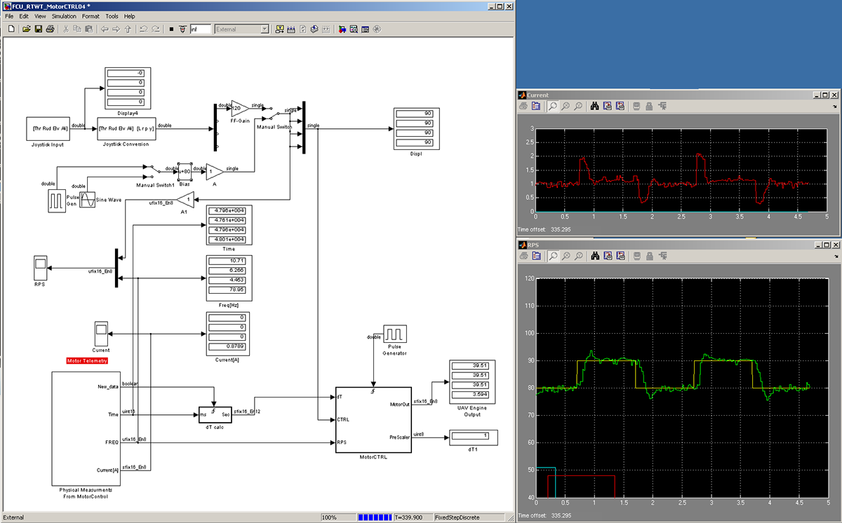
Square wave: Amplitude 80 to 90 RPS, Freq: 0.5hz. Response time is down to ~100ms
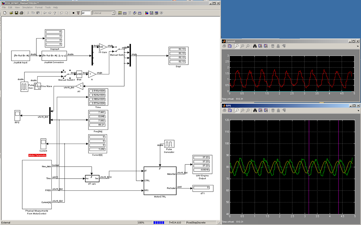
Sine wave: Amplitude 75 to 85 RPS, Freq: 2hz. Response time is down to ~100ms

Open loop results present the following:
- RPS measurement of the 4 quad motors with the reference step control signal.
- Long (~250ms) inertia delay + Dead-Time delay of ~100ms (I need to investigate the source of the 100ms Dead-Time delay)
- It can be clearly seen that each motor has different rotation-speed.

Upper graph - Current consumption of each motor
Lower graph - RPS measurement of 4 motors with the reference step RPS and step control-signal.
Close loop results present the following:
- Very short setup time of ~50ms + Dead-Time delay of ~100ms (I need to investigate the source of the 100ms Dead-Time delay)
- All motors have the same dynamic and steady-state response.
Except some overshoots and underdumping issues - I think it performs very well.
I am currently working on other projects (Baby needs a new pair of shows... ;-) ) But I hope to continue soon...
Comeback After 5-Years!
Today is the 25/11/2016. I left the Quad-Rotor project for something like ~5 years. On this period of time I did many things :-):- 1x more kid :-)- Different interesting projects for different companies.- Improved my RTOS kernel.- Gain more experience in C programming (Naturally).- Developed the Smart-Logger that grow into the Smart-AHRS unit.- Improved my skills in mechanical design and 3D-printing.- Learned to develop in Python (including GUI).- RPI (of course).- Developed the Smart-AHRS (I am going to use its embedded version)
I decided to completely drop Matlab and its generated-code from my project. Matlab is a great tool for development and it made the development much easier until now. But at this point I feel I am using it more as a replacement for writing my own code and PC-GUI-Interface.
I decided to completely drop Matlab and its generated-code from my project. Matlab is a great tool for development and it made the development much easier until now. But at this point I feel I am using it more as a replacement for writing my own code and PC-GUI-Interface.
Since I have these abilities. I will go a head and rewrite the functions. But most important, develop the entire PC-side GUI interface for debugging and controlling the Quad.
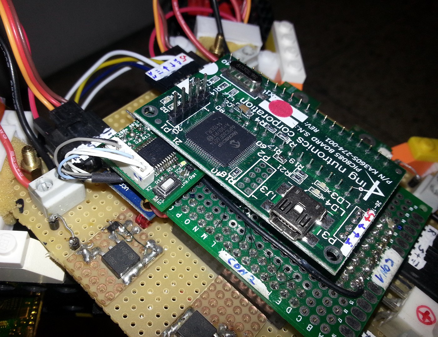
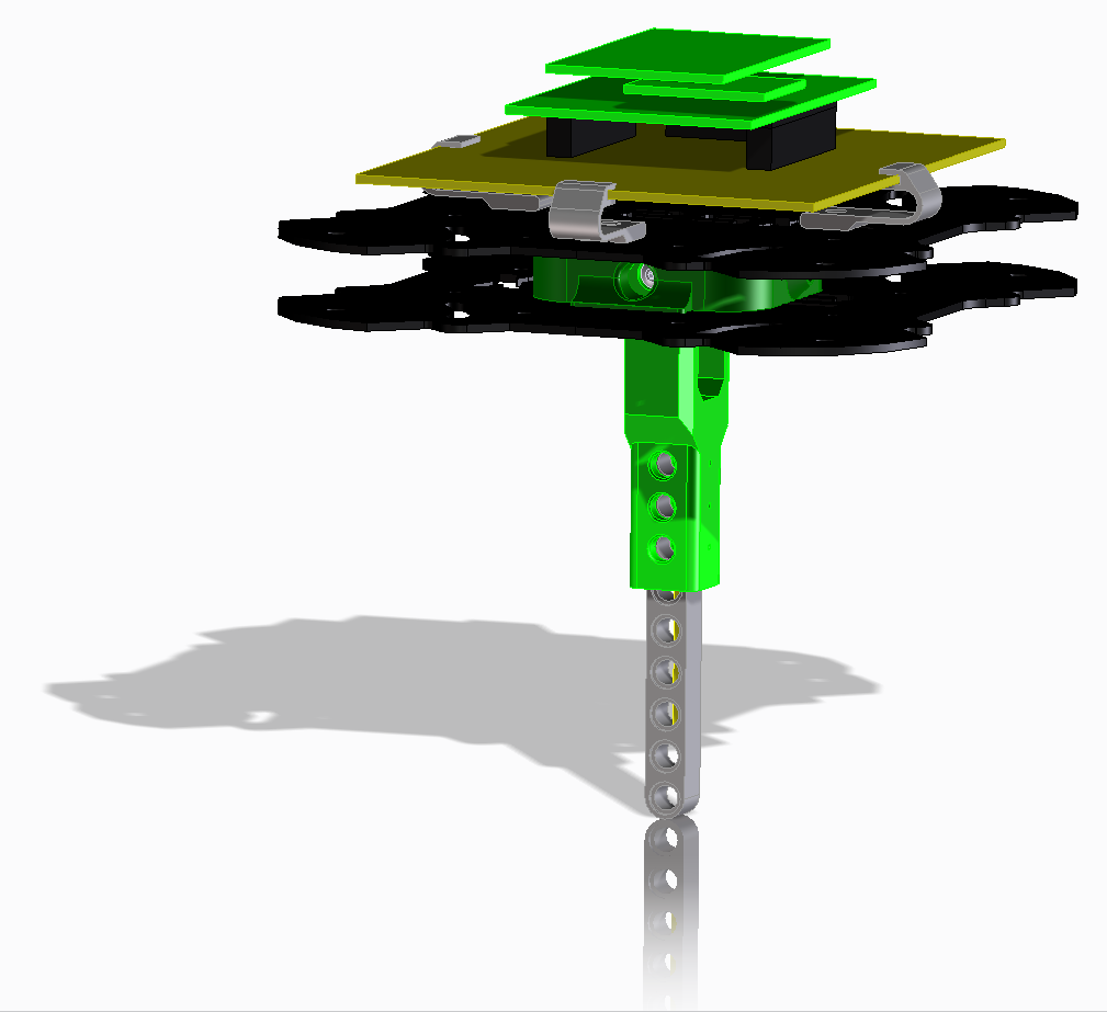
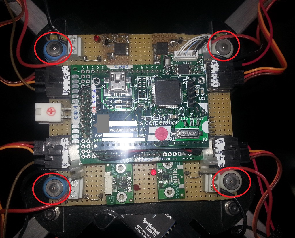
Improved Flight-Controller electronics:
1. AHRS is done by the Smart-AHRS module with a dedicated processor - Top-Left (@200hz integration).
2. Motor-Control and Flight-Control are done on the dsPIC30F module - on the right (Borrowed from a different project).
3. The Power-Distribution board (Bottom) is the same.
4. Motor RPS is taken directly from the BLDC-ESC.
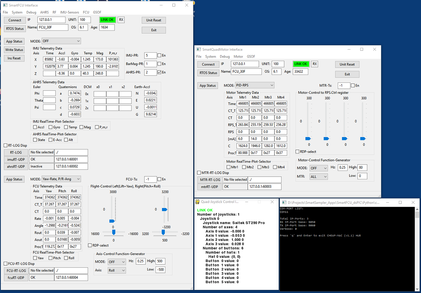
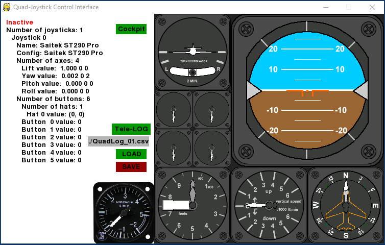
Four separate applications that each communicates to a specific or multiple process on the Quad-Flight-Control program.
Left: AHRS-Telemetry and Flight-Control telemetry and control.
Upper-Right: Quad-Motor-Controller telemetry and control.
Middle-bottom: Joystick control that sends command to the Flight-Control-Process.
Bottom-Right: Bridge application between TCP to the Quad internal network-protocol (via blue-tooth or any byte based steaming protocol).
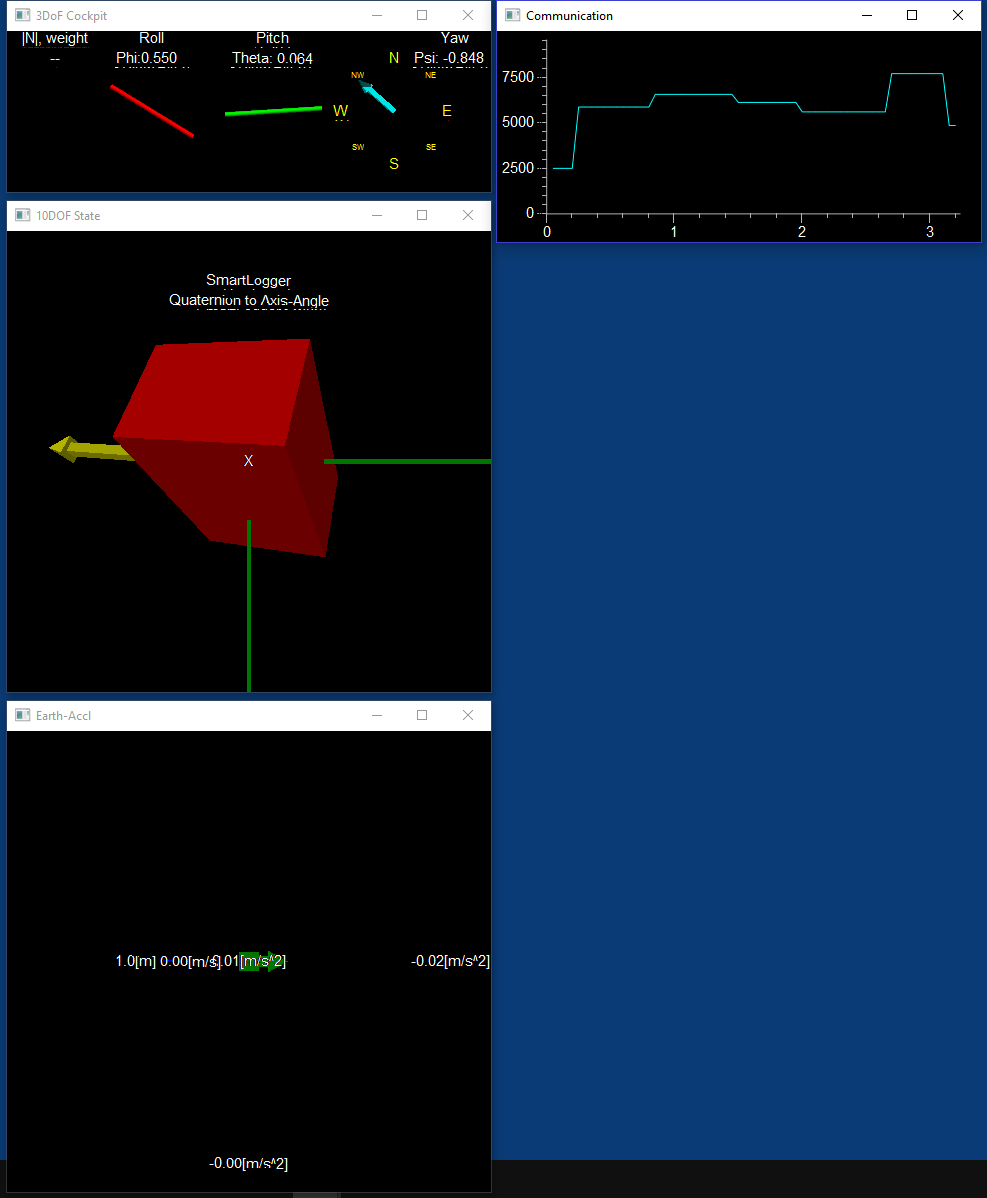
a separate Python application (using VPython module) that represent the AHRS Quaternion or DCM as a 3D object.
This application was developed especially for the Smart-Logger & Smart-AHRS projects. Great for debugging!

Improved the Lego frame by adding a 3D-Printer motor mountings.
The Flight-Control-Loops are not fine tuned yet. But everything looks O.K. and the quad performance (stability + respond) has improved.
Changing to an aluminum frame (X525)
At first I thought to keep using the LEGO frame until after the first stand-alone hover test. But as I increased the RPM of the motors during a thrust test I noticed a significant increased in vibration that caused several things:
1. Prevent from the AHRS to converge on a correct result. In other words the weight of the accelerators results became low and drift started to accumulate.
2. The frame structure started to disassemble over time.
But first I need to design a 2DOF gimbal that will connect the X525 to my LEGO stand. So that is what I did.

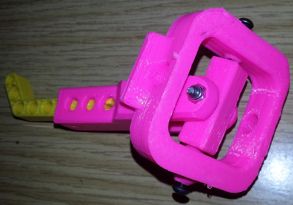

The X525 Frame after embedding the 2DOF Gimbal pivot inside.

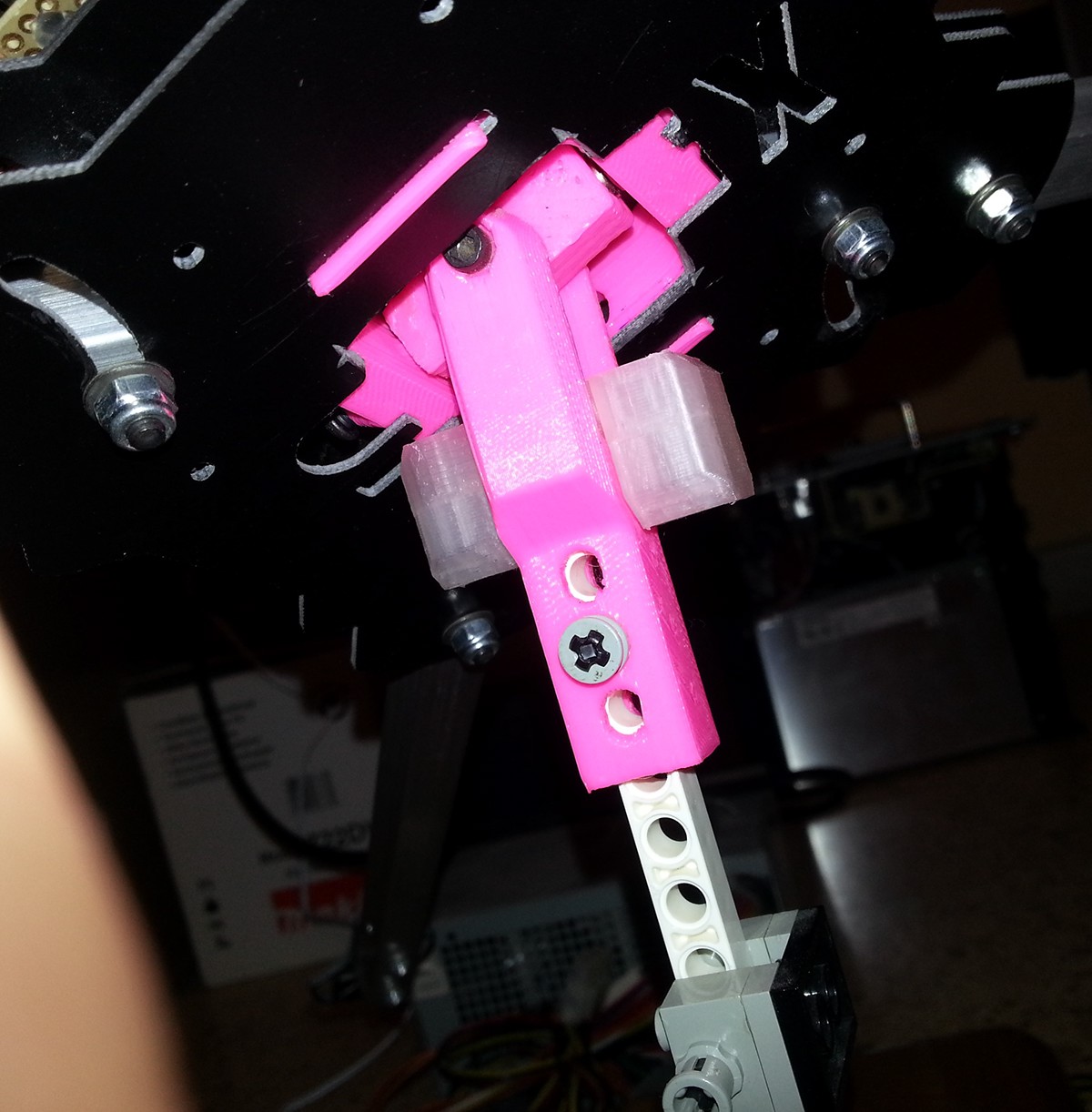
The X525 with the pivot is secured to the Lego stand by a Lego Axle.

The special mounting connectors that connects the electronic board to the X525 chassis.

The fully assembled X525-Quad
X525 test on the new JIG.
I also fine-tuned the control-loop parameters relative to the previous video (The one on the Lego-Chassis).
Vibrations!!!
It looks like anything complicated in this project. When I was preparing for the 1st test flight I decided to test the Quad on the JIG at high RPM. Just to simulate that the motor & control-loops are performing good at different working point then I experimented in.
A few seconds after I increased the RPM I noticed that the Quad starts to bank to the side. After investigating this issue I discovered that the vibrations have devastating effect on the accelarometers.
Wrong or too noisy readings from the Acc will cause the AHRS to give wrong and drift attitude estimation.
So, I am back in the Mechanical Engineering chair need to find better vibration isolation for the AHRS.
I disassembled few old CD-Drives - They usually have good & small vibration isolators.
Also watch few youtube videos about how to balance the BLDC-Motors (I did not know you should).
I used an old CD-Drive vibration-Isolators for mounting the FCU & AHRS on the Quad frame.
Developing the QuadTan (The smaller version)
Here is a link to the "QuadTan" project
The more I think about the test flight the more I understand the logistic problems that are involved with it:
- Finding a big open-space out-side.- Arranging the electricity and PCs.
- Doing it safely (seriously, some one can get injured)
- Doing it safely for the Quad (Minimum damage if fails)
- Good weather. Not too sunny, Not too cold, Not too windy (Army days are over - yes I am spoiled now).
So I was thinking that it would be nice if I had a miniature version:
- It will not be dangerous to me.
- More robust if crashes.
- Easy to hold, test & feel.
- Can be done in my working room / lab.
I ordered a Tarot-120 with 4x BLDC motor, ESC + props.
Made a smaller FCU electronics.
- FCU (PIC6012).
- Smart-AHRS (as before).
- Removed the Closed-Loop Motor-Controllers (I will run them in open loop).
- Same wireless communication.
The nice thing is that Firmware is the same. So this test is going to be good validation for my Quadol design too.
And here it is (See the project that includes many test flights):

The new QuadTan test platform :-)
SmartAHRS embedded version is located on the left (back side of the Quad)
FCU is the lower board
Bluetooth is on the bottom side of the Quad-Frame
First Test-Flight! (Soon...)
FOR THE FIRST TEST FLIGHT OF THE "QUADTAN" FOLLOW THE LINK BELOW:
1. Securing the Quad.
2. Dead-Man switch.
3. External power-supply.
Altitude-Stabilization Control Loop & Real-Time Graphics-Cockpit application(1st developed for the QuadTan)As I mentioned previously, I added a Vario-Inertial capability to the new AHRS.In general it is a basic Kalman filter on the Barometer and vertical acceleration output (in earth axis).The Kalman filter output consist of the following filtered measurement (estimations):- Altitude.- Vertical-speed.- Vertical acceleration.
By using a simple dual PID-Control loop on the vertical-speed & altitude. The Quad altitude can be greatly stabilized.This feature can be activated by the pilot at any time with a press of a button (or remote command).
By using a simple dual PID-Control loop on the vertical-speed & altitude. The Quad altitude can be greatly stabilized.This feature can be activated by the pilot at any time with a press of a button (or remote command).