
Furniture Factory
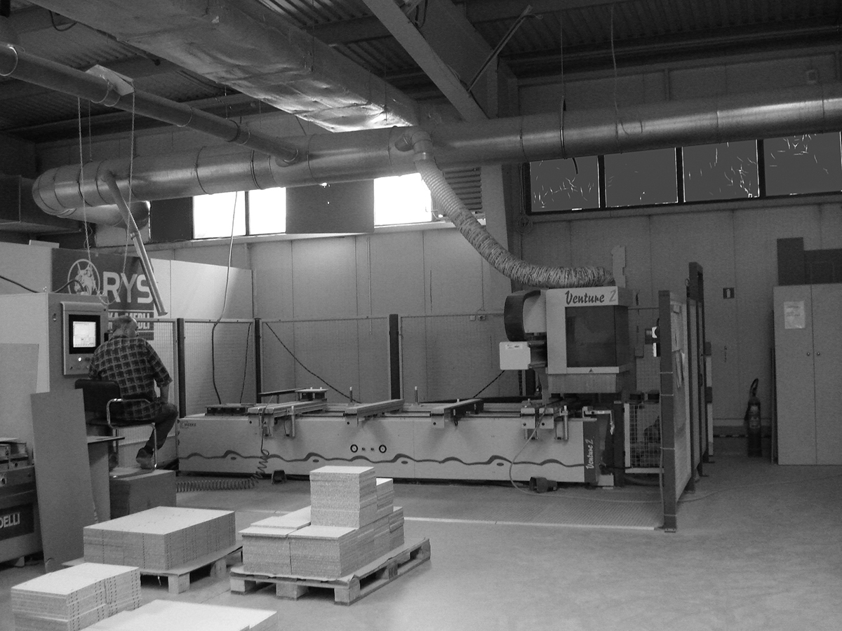
Design process started from developing functional scheme of factory including technological process and manufacturing stages. On-site visit in the one of the biggest furniture factory in Cracow showed complexity of the manufacturing processes and spatial arrangement. The challenge here is to link different but associated facilities: office, the representative space and the production hall. Main design ambition is to combine production hall and office facility within one consistent space. At the same time maintaining the optimum operating conditions for both parts.
Main characteristic of the production hall is linear flow production type. Flow methods mean that as work on a task at a particular stage is complete, it must be passed directly to the next stage for processing without waiting for the remaining tasks in the batch. When it arrives at the next stage, work must start immediately on the next process. In order for the flow to be smooth, the times that each task requires on each stage must be of equal length and there should be no movement off the flow production line. In this example of furniture fabrication is composed of two flows: Incoming intermediate products flow and outcomming products flow.

Programm Accommodation


A streamline is a path traced out by a massless particle as it moves with the flow. It is easiest to visualize a streamline if it move along with the body (as opposed to moving with the flow).
When fluid is flowing past a solid boundary, e.g. the surface of an aerofoil or the wall of a pipe, fluid obviously does not flow into or out of the surface. So very close to a boundary wall the flow direction must be parallel to the boundary. At all points the direction of the streamline is the direction of the fluid velocity: this is how they are defined. Close to the wall the velocity is parallel to the wall so the streamline is also parallel to the wall.
When fluid is flowing past a solid boundary, e.g. the surface of an aerofoil or the wall of a pipe, fluid obviously does not flow into or out of the surface. So very close to a boundary wall the flow direction must be parallel to the boundary. At all points the direction of the streamline is the direction of the fluid velocity: this is how they are defined. Close to the wall the velocity is parallel to the wall so the streamline is also parallel to the wall.

The figure above shows the computed streamlines around an airfoil and around a cylinder. In both cases, we move with the object and the flow proceeds from left to right. Since the streamline is traced out by a moving particle, at every point along the path the velocity is tangent to the path. Since there is no normal component of the velocity along the path, mass cannot cross a streamline. The mass contained between any two streamlines remains the same throughout the flowfield.

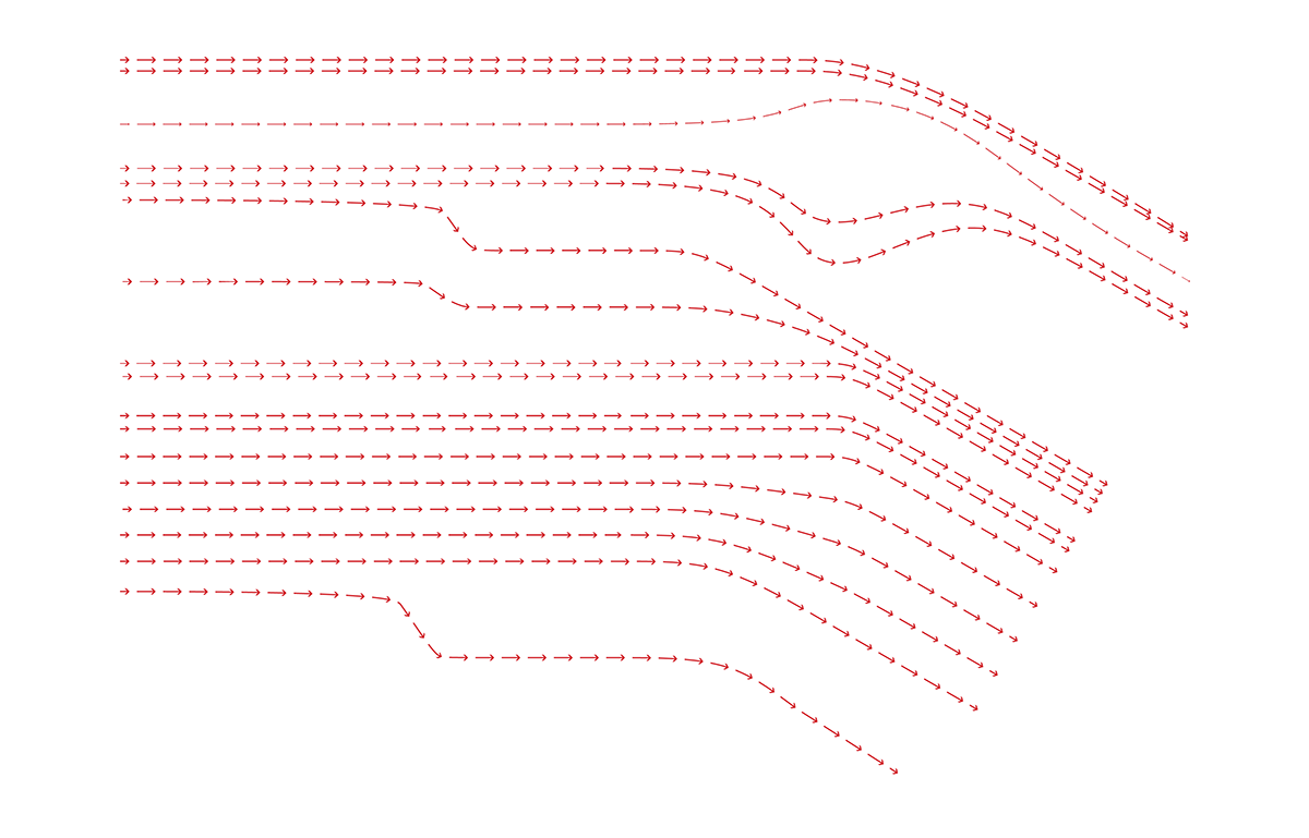
Fluid flow is introduced inside building boudry. Oval bodies were placed as a resistance to fluid flow. Solid bodies are placed in accordance to specifitc building functions. This workflow cause streamlines friction. Cartesian grid were deformed accordingly to the streamlines distortion.
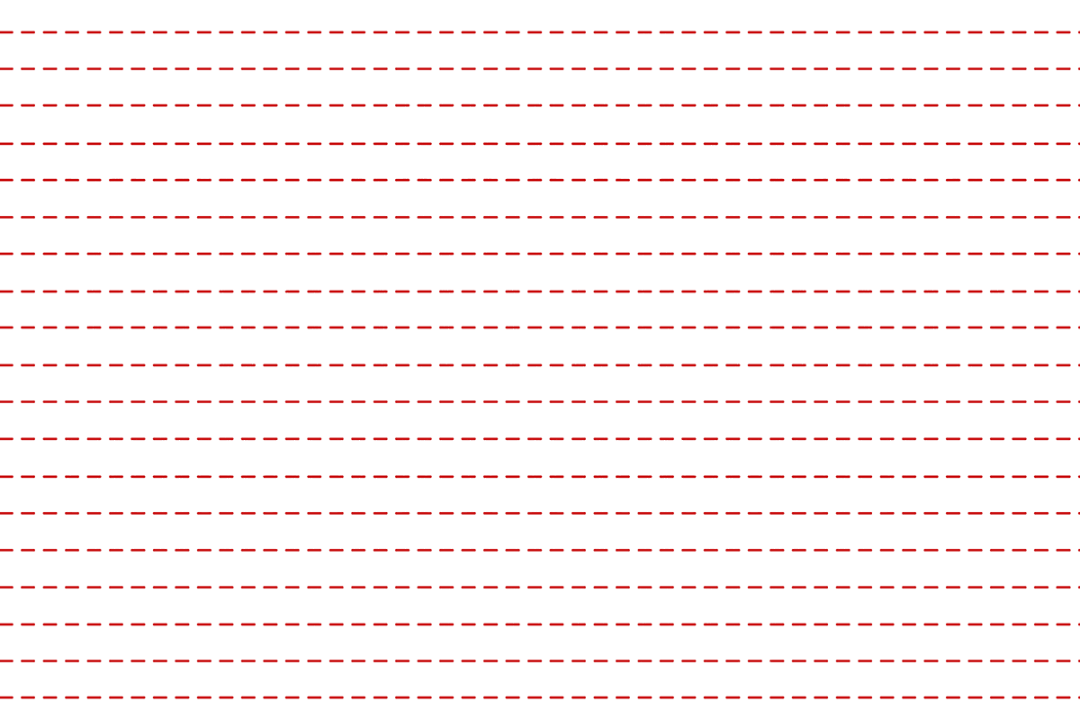
Structure grid introduced inside fluid flow.

Structure gird distorded accoring to the vector of streamlines. The Structure grid is strethed where solid bodies were places. This provides an visual distinguishment for the end form.

Construction beams model

exploded isometry diagram
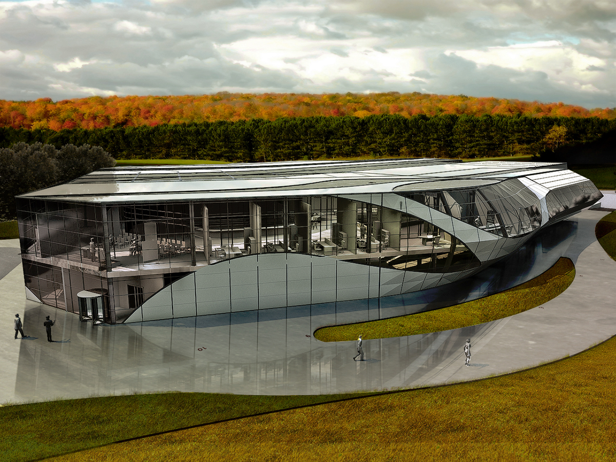
perspective view

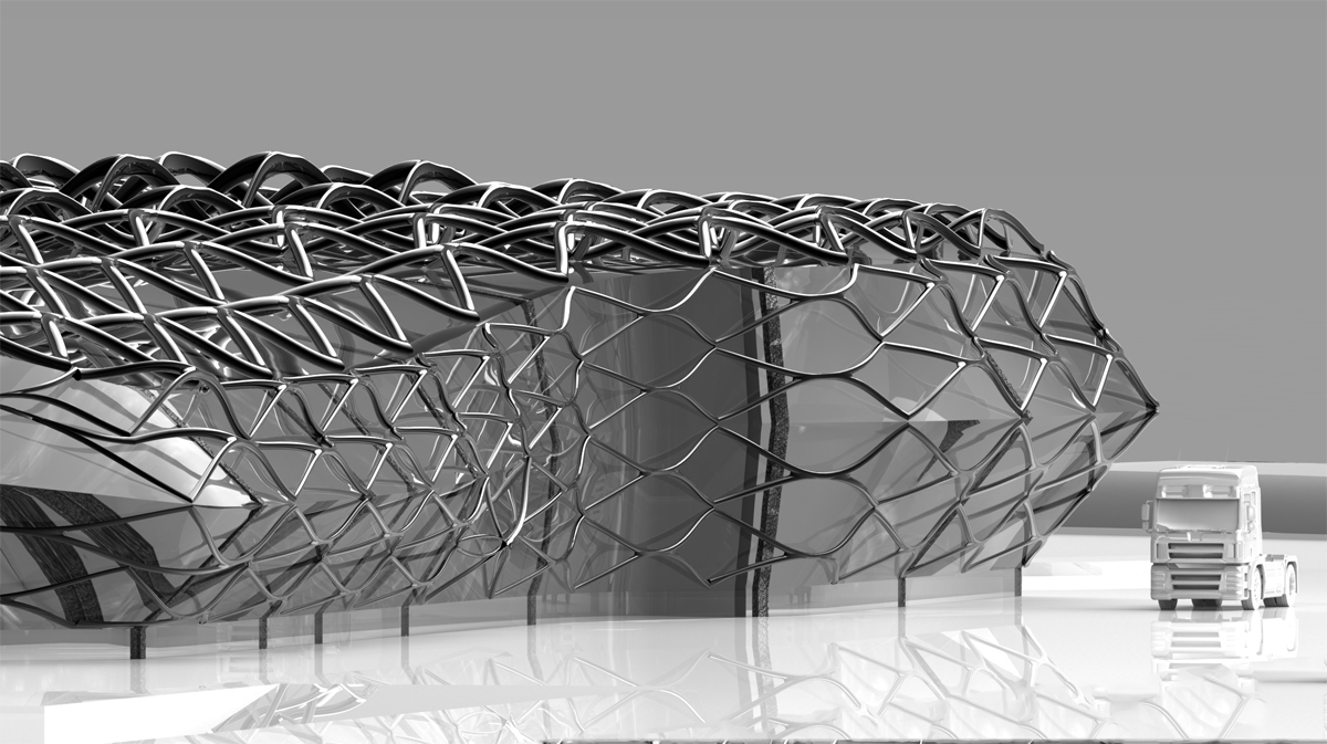
strucuture view after fluid deformation

exterior panels enclosure
Stage II - Project opymalisation
The main driver in designing a factory building is its ergonomic and workflow optimisation . In this case challenge was to optimise previous design double curved surface enclosure and provide sufficient amount of natural light inside office rooms.
The implementation of freeform shapes in architecture is an area which encompasses great challenges in engineering as well as novel design ideas, and which consequently has high public exposure. However, the geometric basics of realizing double curved surfaces as e.g. steel/glass constructions with planar faces remained largely unexplored. Planar quadrilateral faces and true freeform geometries seemed mutually exclusive. Only recently the high potential of optimized mesh geometries has been realised.
The implementation of freeform shapes in architecture is an area which encompasses great challenges in engineering as well as novel design ideas, and which consequently has high public exposure. However, the geometric basics of realizing double curved surfaces as e.g. steel/glass constructions with planar faces remained largely unexplored. Planar quadrilateral faces and true freeform geometries seemed mutually exclusive. Only recently the high potential of optimized mesh geometries has been realised.

Ground Floor - Display Area

First Floor - Administration Area

First Floor

Ground Floor

