
Uniti One Three-Seater Production Intent Prototype 2020
Design Lead (Exterior / Interior), Polygon modelling: Marcelo Aguiar
UI/UX: Bo Johansson Möller
Class A Surfacing, Design team support: Henrik Björkvald
3D Renders:
Exterior - Surface model by Henrik Björkvald
Interior - Polygon model by Marcelo Aguiar
Design
Marcelo Aguiar
The design of the Uniti One was revised in three different aspects:
- Further development and problem solving of a number of styling issues;
- Changes necessary to make the vehicle fit the new briefing and company strategy;
- Changes necessary to comply with M1 regulations, which is the category the current model shifted to.
Using the previously established DNA as a base the opportunity was taken to purge unnecessary elements and refine the design.
Coherence and consistency were the main goals in this iteration: the design should appeal to the viewer both at logical and emotional levels, when the features of the car work together with the overall look and feel, combined into a consistent whole.
The design process was dominated by a productive dialog between the Design Team, the Engineering Team and Surface Modeller, Henrik Björkvald.
Proposals were developed from sketch, to Polygon modelling. Meshes were analysed by the Engineers and Modeller and their feedback integrated. The refined solution was then checked in VR to assess its aesthetic validity.
Exterior
An all-around dark base replaced the previous front spoiler, rockers and rear bumper to lower the visual weight, to give it a product feel, and to better fit the concept of a pod-like shared vehicle.
The body is clearly divided into three distinct parts - the base, body panels and greenhouse - crisply separated by fundamentally straight lines with slight variations to integrate design features and components. One example is the kink above the quarter-panel which is the only variation in an otherwise straight belt line. It houses the iconic Streak with the "U logo" and generates the space for the taillights towards the rear.


The headlight cluster was the component that was subject to more profound developments due to M1 light source visibility regulations. A wing-shaped DRL replaced the Blade DRL from the previous model. The two bulbs logic transitioned to a single BI-LED lamp, which became the main element in the cluster, changing its shape by subtracting its projection from the "surrounding material".
A HVAC intake was integrated into the cluster, emphasising the bulb element while adding depth.


The taillights also evolved to fit into the new exterior, to comply with M1 regulations, and to become feasible given the necessary manufacturing techniques.
Three main elements sit inside the cluster housing: Position and Stop lights, and Indicator lights (made of white frosted acrylic and back-lit by an LED strip of their respective colour) and an natural colour aluminium piece underlining the Indicator pieces.
The horizontal lines emphasise the width of the car.

Final renders


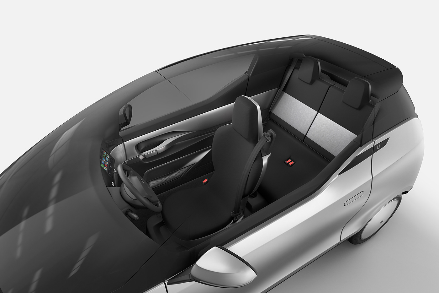
Interior
The most significant change in the interior was the number of seats. The production version has a three seat layout with a centered driver position. This layout was chosen to fit scenarios like shared mobility, ride hailing and delivery vehicle.
Two folding seats in the rear means the width of the car increased with nevertheless immense benefits, such as the possibility to easily switch from a delivery car layout (1 driver + cargo) to a ride hailing layout (1 driver + 2 passengers).
The interior was developed from the 2017 Concept, while integrating production parts and requirements.
The main theme of a Protective Ring around the occupants was kept and emphasised by giving more relevance to the metal trim below the Ring. From it, shapes are created for the door cubby and handle that speak to each other, contributing to the consistency of the whole.
On the dashboard, the three-screen array Horizon Panel was replaced by a front panel that houses also three screens, but each with its own functions.
The steering wheel shows an element already used throughout the exterior - the pill-shape - and integrates an element of asymmetry - the Uniti logo - for a product feel.


Final renders


Delivery car scenario
One of the use cases for this model is gig-economy Urban utility vehicle.
The rear seats are simple to fold down and lay completely flat. Once flat, the Uniti One turns into a single-seater with a generous 760 litres of usable cargo space. With additional storage beside the driver, longer packages can fit in the Uniti One with ease.

A-Class Surfacing
Henrik Björkvald
Surfacing was carried out with a dynamic dialog between the design team and production engineers, with sketches and 3D polygon sketches as a base.
While both techniques are extremely useful, the differences between Polygon and NURBS modelling are immense and at a fundamental level. Yet they complement each other in the design process.
Polygon being much quicker, less constrained and focused on Rendering / Visualisation, widely used in the 3D community to create creatures, animated figures or other things that do not go to production. These tools enable sketched models that look great, especially from a distance.
NURBS surfacing is the base for everything in production phase, often referred to as CAD. Originally when work was done on drawing boards, it was digitally remade into 2D CAD, with lines, arcs, splines etc. Later in the mid-90's 3D software became mainstream and enabled surfacing between the curves and later solids from the surfaces. These tools are much more precise, much more advanced in some ways, usually much slower and in many ways limited.
Then there is CAID, concept modelling and A-Class Surfacing, which is what my part in the project was about. I work in a self-taught technique, cherry-picking a bit from Polygon and NURBS to be able to sculpt as freely as possible and also do changes late in the model, updating in the middle or even after the major surfacing job is done leads to seeing the car more clearly, and tweaking on a more "real" object, without loosing speed. Ideally the end result should be a model that can be used for 3D renderings as well as production/tooling when complemented with information from the engineering team.
The images underneath are more of work-In-progress, usually generated (for me or Marcelo) to get a proper understanding of how the surfacing/forms behave. As we work in a extremely digital flow (using VR instead of clay modelling or similar luxuries that we would love but had no access to), we had to find ways to see if our creation looked as intended before we actually saw it in the real physical form.
For the "Beauty shots" or other more impressive images, please refer to the images Marcelo posted as they use the final A Class forms, my work is in essence to make sure the end result and in this case the 3D model is of the highest level, not actually shining with pretty pictures 😉.
Exterior
We took off from the 2017 concept model, and the Uniti team had worked a fair bit after those days (I was involved back then too, but as usual came in at crunch-time to get it done). The size was different, the concept as well and more than that - we actually had production engineers that we had to deal with to make sure what we created could be produced, and to the specs needed (tooling, cost, quality etc.).
Some things were locked down, some we had a lot of freedom with, and in my world being able to tweak late, this meant that I could build up the surface strategy/layout for most of it first and tweak later to comply to design and/or engineering suggestions.
As seen on the "time lapse" movie below, the design mesh polygon model is often used as a reference to begin with, with a new look building up in the different world of NURBS surfacing. If there is one massive difference between them that would be that organic forms are so much easier in poly and strict, precise forms make so much more sense in NURBS. Perhaps this is why Class A modelling is seemed a bit like a "Black Art", in order to build forms that look great in formed metal, the modeller really needs to master both sides! I had a massive advantage/disadvantage to other bigger projects in that I was the only modeller, so I had full control, on the other hand the job is quite massive for one. If there were more of me, no doubt individual surfaces could be even more perfected. 95% of the work was done by me in a few weeks.
Zebra pattern analysis was carried out in several instances of the design process to check the validity of the surfaces and their transitions (more than form, for form I prefer a great shader or using vis tools with more real materials, we also used a VR setup a lot). To be honest I work a lot using the CV layout as proof of surfacing/transitions, only backed up in the end with zebra as it gets a bit too much and tend to take my eyes of the overall forms. Zooming in and zooming out, not getting lost in detailing is often harder than nailing a perfect zebra.


The rear quarter-panel represented a greater challenge due to the several elements to be harmonised. It was important to keep the consistency of the "Character Line" while keeping the rear wheel-arch within package limits without losing "muscular attitude". This process resulted in more than 20 iterations until a satisfying whole was achieved.
In the image below you see "my kingdom", the world of splines, math, using as low "CV-count" (the data points that define surfaces and splines) as possible but enough to nail complicated forms. To get it all "right" both manual labour and using software tools is needed, and a structured layout is required. This is quite a common "work in progress" image from what is going on, with everything interacting with everything.

Visualisation tools were used a lot (also VR, sketching etc.) to see what we were doing outside of the normal "CAD-world", to communicate quickly and because it is quick and fun! Perfection was not a major concern at this stage as the purpose was to use the images internally. A great reality check to not get lost in detailing or surfacing, to get the data into another appearance.


For the interior modelling, most of what is said before is the same, even more focus on the overall layout and the modelling strategy had to be set, as there are more constraints, more forms, more details, and since the exterior dictate a lot on the interior. And here we really wanted to make things a little bit easier by locking the exterior before doing too much work on the interior (there were a few hiccups as always but as the exterior was updatable we survived those).
The interior is a bit more tricky in terms of constraints, as the forms and details should be feel comfortable, edges should have a minimum 3 mm fillet radius (due to regulations) that look nice and even, there should be nice splits in between parts that often stack up next to each other in ways that are not ideal, sometimes the modeller is not even in control of all parts. All of this should obviously look intended, ideal, designed and spot on - in the end. For the interior it is a bit less about perfect, large surfaces and more about really hard work to get the detailing in place. There were probably twice as many surfaces and features building them than in the exterior. I actually enjoyed modelling the exterior more, even though the interior was closer to what I am used to outside of Uniti. I guess it would be nice have someone cover and focus on perfecting the details, for the exterior that was fine as is.
I used my own technique again with first building a larger overall form (for the side in this case), then I used tools with intelligence to split it up in a patched layout, modify the overall shape and finally lock up the constraints afterwards. Not sure how to explain this but it means that I had almost complete control of the CV-points (that are the math for the surfaces, nail these and you have perfection), and also had a way to change the overall form afterwards, without starting over. PM me if you are interested..


The image above shows the poly surface model (half the car, to make it easier). First step to figure out a strategy and how to split up the surfacing to have both control and flexibility.
Same surfaces in NURBS, half way through the project, even here I had moved on to split parts to see how they work together, as I use a hybrid modelling technique I can later go in and tweak or move on further into detailing.
"Work in progress" comments, we use these to get the shapes in place, depending on who you work with (the modeller) learn when you need to "copy" and when and how to follow "design intention". With Marcelo, we have built an understanding, meaning I follow but go with my gut to improve, or even follow some kind of surfacing flow, then we keep what feels better and tweak what didn't work. This might actually be crucial as poly and NURBS behave in completely different way (copying is hard or even impossible, and at times not the design intention), hopefully we build on the best of both.

Again most of the work was done by classic "Class A", using un-patched surfaces with surface breaks where it makes sense, much of the surface layout was done first, and tweaked with enough detailing in place and some changes/tweaks to improve the main form was made after the B surfaces (flanges, thickening etc.) was constructed (as we could). As I did both the visible and the less visible stuff I could be in control and make sure it all looked okay and actually worked for downstream.
Thank You!


