MORPHEUS
Zaha Hadid's parametric masterpiece, recreated

When delving into the world of possibilities offered by parametric design and logic-oriented modelling, I came across The Morpheus Hotel: From Design to Production, a webinar giving an insight on the design, coordination and construction process of the cited architectural and structural achievement recently built in the Chinese SAR of Macao.
The fact that all different phases of the project retained the implementation of the parametric approach stood out and inspired me to try to recreate this project using (most of) the same tools and the iterative design methodology of the original project, therefore pushing my skills and the way I approach each step involved in the re-creation process and its inherent challenges.


The Approach

The first element I tried to recreate was the 2D base grid for the façade and the members connections. A simple square grid was created and then processed using a sinusoid graph mapper to simulate attraction based displacements. The connections were created using data selection rules and custom displacements were applied on the bottom nodes.


The 2nd step consisted of creating the overall shape envelope of the building, which is not an extremely easy task using Rhinoceros native tools. I decided to try the T-splines plugin, which was also used in the original project. After following some tutorials online to get a grip of the plugin, it was fairly straightforward to model the complex free-form shape with the voids by manually drawing the mesh and creating an extrusion. Only the middle part was created in T-splines - the rest of the envelope being pretty straightforward to achieve with grasshopper and a solid union operation. I didn't spend much time refining the mesh to achieve a carbon copy of the original form, since this wasn't the goal. But a little more attention to detail in this phase would have saved me some extra work on later steps.

The most complicated steps were those related to trying to wrap the 2D grid around the overall shape and its free form part. Since the voids don't follow any particular geometric logic, any 100% rational grasshopper routine would fail to achieve a flawless projection of the members while maintaining their connections and not giving geometrical aberrations. I've tried several different methods - from 45° projections to converting the voids to UV untrimmed surfaces and drawing geodesic grids on them. While some of these methods might have worked for the upper void (which presents a fair degree of symmetry), they would fail on the other ones, where the grids' logic could not be rationalized without some manual intervention. This means that a grasshopper routine was all the same used to wrap the grid around the voids and create the connections, but any modifications on the original T-splines shape would force the routine's parameters to be changed manually, coupled with visual inspection for it to be coherently adapted to the new shape.
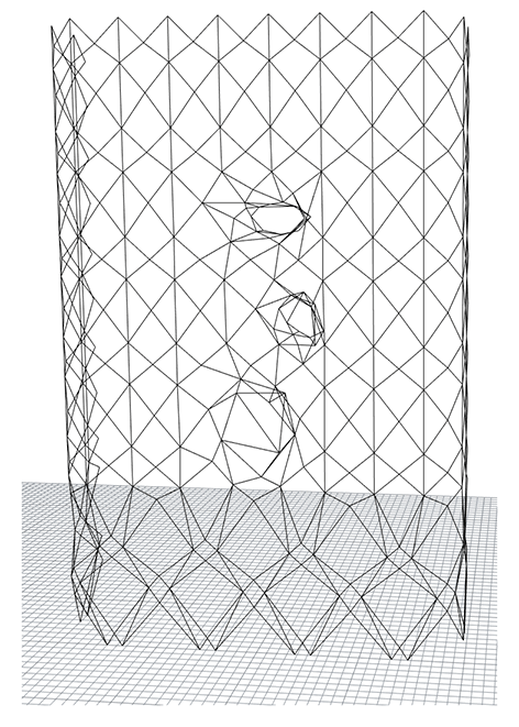
This routine was based on morphing the grid's nodes onto the voids and deciding which connections were going to be preserved. Once these connections were established, a Kangaroo physics routine was used to create the geodesic-path-based members based on a mesh attractor with variable strength. The issue here is that, since the T-splines shape presented areas with sharp curvatures, the members wrapping around them would sometimes present considerable torsion or deviating shapes that wouldn't make much sense structurally and aesthetically. So, instead of changing the T-splines shape, I opted to apply the routine with moderate attraction strength (shown in the animation above), which created members with softer forms and not "glued" to the original shape on every point.
This approach meant that the original shape would now have to be adapted to stick to the new members, which wasn't exactly straightforward but could be achieved by creating patch surfaces with the new members as boundaries. This step is essential for the later panelling and slab adaptation steps. The easiest approach would of course be based on just having designed a more refined starting shape in the first steps while anticipating these issues, which would have also avoided the secondary downside of the reduction in the voids' volumes by a small margin.
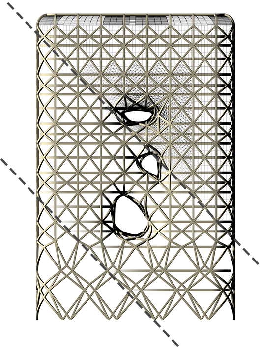
Once the members were wrapped around the voids and each individual surface bounded by them was extracted and joined to create the new overall shape, the next step was deciding on the panelling logic. To simplify this process, I decided to create triangular meshes on the freeform area and surrounding non-planar surfaces, while the remainder of the envelope would be covered by simple rectangular panels. Various triangulation methods exist, and, while easy routines such as the lunchbox plugin diamond panels creation can be applied to untrimmed rhomboid UV surfaces, undesirable result would be generated when applied to trimmed triangular surfaces such as the ones split by middle members in this project. These required circle packing routines or similar Kangaroo physics iterations to approach the desired equilateral triangle distribution.
The slabs were created using solid intersections and curve pulling routines on Kangaroo to make sure they didn't overstep the envelope on areas where the mesh could behave non-optimally.

The final step consisted of creating an envelope shape for all the nodes while taking into account the overall alignment, relative torsion and angles between the different members connecting at each node. Once again, I was only interested in achieving a coherent and rationalized form that could be further refined under its parametric nature to achieve the perfect connection at each node, by using optimal radius and forms depending on the angle and the length of overlapping between members. I didn't apply the proper refining since it would be time-consuming and would go beyond the purposes of this project. As so, these connections only work optimally on about 90% of the nodes that are in the threshold of complexity of the applied algorithm. These could be corrected in the future with special rules applied to the nodes outside of this threshold. Nonetheless, the achieved result was satisfactory.

The above animation shows the step-by-step process in a close-up from one of the voids angle. From this distance, some of the incoherences with the connections and the slab overstepping are more visible, but they could be easily corrected with some refining if the project ever entered into the structural documenting and optimization for construction phases. All of the basic objectives I contemplated for this project were achieved, and I was able to work with several plugins and environments I didn't have any or only basic knowledge of.


