Introduction:
Module 3 was divided into three parts;M3.1,M3.2, and M3.3. In this behance, I go through all of the steps of each part. This project required me to create various models, diagrams, and do research. All of these requirements are found below in detail.
M3.1: Lather, rinse, repeat...
Part 1:
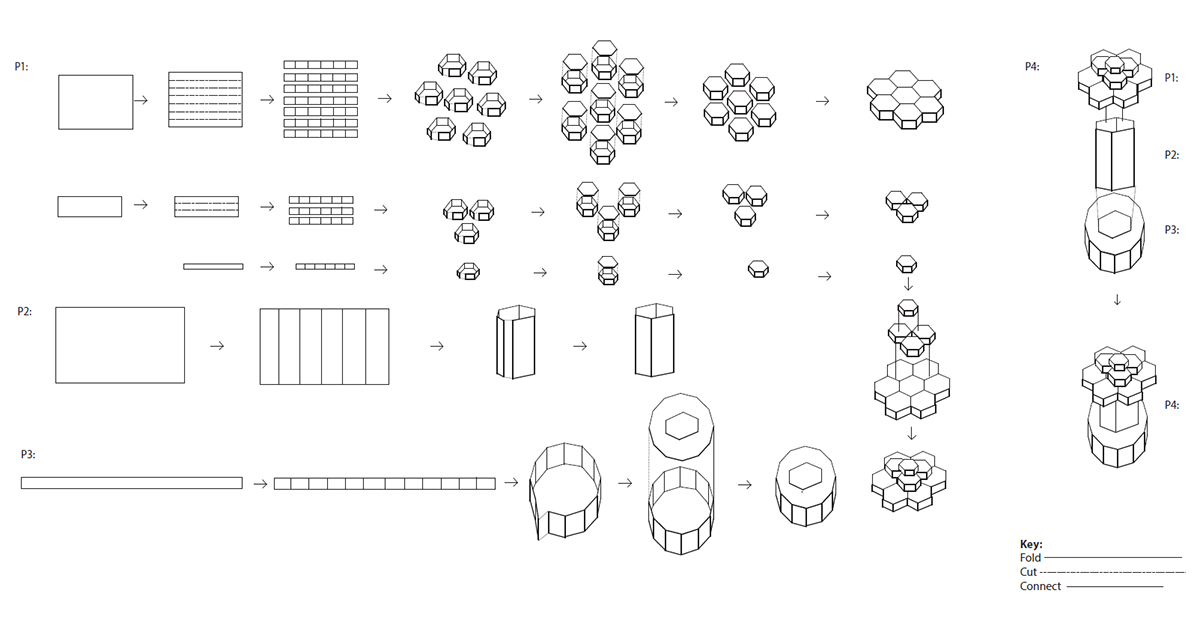
In part 1 of M3.1, I was assigned a design principle and asked to pick found design techniques. The principle I was assigned was Balance. The techniques I chose were Weave, Fold, Perforate, and Pinch.After researching the defintions of Balance and the four techniques, I was asked to create 12 models (3 models for each technique).Below are the defintions and photos the 12 initial models I created.
Balance: ways in which elements (lines, shapes, colors, textures) of a piece are arranged, can be symmetrical where elements are given equal weight from an imaginary line in the middle of a piece, can also have asymmetrical balance in which elements are placed unevenly in a piece, but work together to produce harmony.
Weave: form by interlacing long threads passing in one direction with others at a right angle to them.
Fold: bend over on itself so that one part of it covers another
Perforate: pierce and make a hole or holes in, make a row of small holes so that a part may be torn off easily
Pinch: grip something tightly and sharply between fingers, compress

Initial Weave Models.

Initial Fold Models.

Initial Perforate Models.

Initial Pinch Models.
Part 2:
In Part 2 of M3.1, I was asked to create 20 more models (5 more of each technique).Found below are photos of these models.

Improved Weave Models.

Improved Fold Models.

Improved Perforate Models.

Improved Pinch Models.
M3.2: S,M,L,XL
Part 1:
In part 1 of M3.2, I was asked to pick my favorite 3 models, photograph them, and create collages on photoshop using the edited images of the models. I was asked to keep in mind the concept of small, medium,large, extra-large. I also was asked to incorporate repetition and rhythm in the computer generated designs I created. My favorite models were 2 pinch models and 1 fold model. Found below are the designs I created for each model.

Three designs created using one of the pinch models.

Three designs created using the other pinch model.

Three designs created using the fold model.
Part 2:
After creating 9 computer generated designs, I was asked to replicate one of the designs by making a physical model of it. I chose to create a model based on my fold designs. I liked the hexagon pattern and saw potential in it. However, by actually having to make something, the design changed from the original photoshop design. As a result, I was asked to make a model of the new design in Rhino and export it to Illustrator to add lineweights. Below are images of the model making process, the model, and the computer model of the new design.

Photos of the model making process.

More photos of the model making process.

Photo of final model for M3.2.

Final computer model for M3.2.
M3.3: Disciplined Surface
Part 1:
In M3.3, I was asked to take my model from M3.2 and assign a use and orientation for this design. This required me to make many decisions and do research. I also was asked to create a plan, section, elevation, and other various diagrams of the future model. I also created a rough physical model. Found below is my detail use list, diagrams, renders, and the physical model.
Detail Use list:
Use: Eat
Orientation: horizontal, table top and structure
Design proposal: Hexagonal shaped restaurant tables that curve to create a half circle with empty space behind for 3 chef stations to prepare and cook food
-In this design, the bottom layer is made of 6 hexagons, in which four hexagons provide space for place mats, and two provide counter space for the chef
-The four bottom place mats will include the mat, plates, utensils ,cups, napkins
-Seating will be bar stools that will provide space for 12 people
-The two hexagons that will be provided for the chef will be grills/stove tops to cook the food
-The middle layer is composed on three hexagons, two of the hexagons will be used by the users, and one will be used by the chef
-The two used by the users will have various ingredients for the Chinese dishes that the user will put on their plate/bowl and hand to chef once they are done making their choices
-The one hexagon for the chef will be counter space to place plates/bowls on while chef is cooking ingredients and to place cooking utensils on
-The top layer is composed on one hexagon that will be used mainly by the users. This will provide space for condiments (salt, pepper, and soy sauce), beverage pitchers, etc.
-Diamond void space could have an added table top onto it to allow for more counter space for food, drinks, utensils or could be used for the chef to pass the cooked food to the user
Tectonic: Because of the hexagonal shape, the tables with fit together at the corners, creating a diamond shape void.
-On the table top, the bottom layer is made of 6 hexagons that connect to form another hexagon in the center
-The middle layer is made of three hexagons that connect to form a triangle in the center
-The top layer is made of 1 hexagon strategically placed in the center, but is not in like with the center bottom hexagon
-These three layers simply are placed on top of one other
Scale: The table will be 4 feet tall at the highest peak, the table top for users will be 3.5 tall, the remaining two layers will be 3 inches tall each.
-The length of each side of the hexagons will be 1 foot
-The surface area of each hexagon is 2.6 ft2
since the whole bottom layer of the table top is made of 6 hexagons with one in the center, the total surface area of the bottom layer is 18.2 ft2
-The middle player is made of three hexagons so the surface area is 7.8 ft2
the top later is made of on hexagon so the surface area is 2.6 ft2
-There will be 3 tables included in this design so the total surface area of the tables (excluding the chef space in the center) will 54.6 ft2

Plan of initial table design.

Elevation of initial table design.

Elevation of initial table design.

Perspective of initial table design.

Renders of initial table design.

Physical model of initial table design.
Part 2:
After given a critique of my table design, I was asked to do research on restaurant code. After finding all of the requirements for restaurant tables, my design drastically changed. To illustrate these changes, I created more diagrams,including my first algorithmic drawing, and created my first template for Module 3. All of these are found below including my research.
Research:
Bar height: around 42-45 inches
Eating space on table: should be based on frontage of 24 inches and area of approximately 2 ft squared. Should have 24 inches in width and 15 inches in depth.
Footrest: 7-9 inches off the ground.
Space required between seating: 2 feet.
Chair height: 37.4 inches
With this information in mind, my bar height would be 4 feet total. The bottom countertop used for eating would be 3 and 1/2 feet off off the ground. The middle tear would be 3 and 3/4 off the ground. The top tear would be 4 feet off the ground. The footrest would be 9 inches off the ground.
With this new research, the countertop changed the most. I needed to provide more eating space for the restaurant patrons. I doubled the size of the bottom tear of hexagons up to 2 feet. This would meet the width requirement for eating space.I also decreased the size of the second and third tear to provide more depth for eating space. The middle tears hexagon's would have a side length of 1 and 1/2 feet. The top tear would have a side length of 1 foot. The new diameter would then be 16 feet across one way and 8 feet across the other way. I also needed to reevaluate what each countertop's use would be. Instead of having the chefs cook on the hexagon countertops, I decided to have all the cooking take place in an adjacent kitchen. This would leave the counterspace for the chefs to be used for taking orders and adding last minute touches to the food. Also instead of having the middle tear offer food options, it would serve as a place for menus and condiments. I needed to make these changes because I felt there was not enough room for cooking space for the chefs or space to hold food options.
Also in the initial design, the base of the table was too thick. Instead of having three bases, I decided to have one single base that would connect to the middle of the countertop. Also after receiving the suggestion of adding a footrest and researching footrest requirements, I decided to add one around the base of the table.

Plan of final table model.

Elevation of final table model.

Elevation of final table model.

Plan with dimensions of final table model.

Section with dimensions of final table model.

Diagram illustrating the uses of each tear of countertop for the final table model.

First algorithmic diagram.

First page of first template.

Second page of first template.
My first template included too much process, offered no captions or project description, not everything was in scale,and the algorithmic drawing was not organized efficiently. I needed to give my second template a new overall composition and give my diagrams a more accurate scale.
Part 3:
In part 3 of M3.3 I reorganized my algorithmic diagram. I also created a second template by taking off some of
the process, fixing my scales and lineweights, and created a whole new layout.

My second algorithmic diagram.

First page of second template.

Second page of second template.
Project Description:
In Module 3, I was assigned the design principle of balance and chose the design techniques of fold, perforate, weave, and pinch. After creating 32 different modules, I picked one to move forward with. Images below and to the left show the progression of this single model. The single hexagon pattern led to exploration of how to connect multiple hexagon patterns. This led to assigning this module a use. The use I chose for this module was eat. This module would become a table in a restaurant. The teared hexagon structure would be found in the countertops and base structure. After creating a rough model of my initial table idea, I realized that I needed to research restaurant codes and reevaluate what the role of each tear of countertop would be. My final model has developed from my original idea into something very complex. This table featured three tears of countertops, a footrest, and every inch of it has an assigned duty.
User profile:
The user of this design is either a customer at a restaurant who will be eating at this bar styled table or is the chef who will be using the counterspace as a last minute cooking/serving station.
After pinning up my second template, I realized that I need to rewrite my project description, fix lineweights, and organize my algorithmic diagram differently so that it would fit on the page nicely.
Part 4:
In part 4 of M3.3 I created the final versions of my algorithmic diagram and template. I also created the final model of my table design. In this stage of Module 3, I also started to think of what materials the real world version of my table would be. I decided that the countertop would be made out of glass and the rest of the table would be made out of wood. The vellum in the model represents glass while the bristol board represents wood.
The new diagrams and model are found below including photos of the model making process.
Final algorithmic diagram.

First page of final template.

Second page of final template.
Project Description:
In Module 3, I was assigned the design principle of balance and chose the design techniques of fold, perforate, weave, and pinch. The images below and to the left show the progression of one of my fold designs. The single hexagon pattern led to exploration of how to connect multiple hexagon patterns. This led to assigning this module a use. The use I chose was eat and orientation I chose was horizontal. These decisions influenced my design to become a table for a restaurant. The teared hexagon structure would be found in the countertops and base structure. After creating a rough model of my initial table idea, I realized that I needed to research restaurant codes and reevaluate what the roles of each tear of countertop would be. My final model has developed from my original idea into something very complex. This table featured three tears of countertops, a footrest, and every inch of it has an assigned duty.

Photos of the making process for the top tear countertop. I used bristol board and vellum.

Photos of the making process for the middle tear of countertops.

Photos of the making process for the footrest.

Photos of the base and trying to fit the countertop pieces around it.

Photo of the complete countertop from above.

Photo of my final model.

Photo of my final model.

Photos of my final model.
Conclusion:
Some of the comments from my presentation included fixing lineweights on my template and having all of my drawings in one scale. Also they suggeted that I should have created three tables at a smaller scale for my physical model and threw out the idea that I could have made the countertop spin.
Module 3 allowed me to discover new design techniques,explore model making in more depth, and use my creativity to assign my model a use. M3.1 taught me the basics of model making. M3.2 taught me computer skills and further improved my model making skills. M3.3 allowed me to apply my design to a discipline. I enjoyed M3.3 the most because it allowed me to feel like an interior designer. I enjoyed researching the codes and getting very detailed with what I wanted this design to become. I also learned the basics of how to create a well crafted model. I feel this module helped to prepare me for the future by teaching me what the design principles and techniques are, allowing me to build models that apply to my discipline, and instilling in me the importance of scale.
Module 3 allowed me to discover new design techniques,explore model making in more depth, and use my creativity to assign my model a use. M3.1 taught me the basics of model making. M3.2 taught me computer skills and further improved my model making skills. M3.3 allowed me to apply my design to a discipline. I enjoyed M3.3 the most because it allowed me to feel like an interior designer. I enjoyed researching the codes and getting very detailed with what I wanted this design to become. I also learned the basics of how to create a well crafted model. I feel this module helped to prepare me for the future by teaching me what the design principles and techniques are, allowing me to build models that apply to my discipline, and instilling in me the importance of scale.

