Full datasheet can be downloaded from:
http://dl.dropbox.com/u/22843989/Publish/PID_Controller_UG16e.pdf
An enhanced version is currently under development:
-SPI 20Mhz control channel
-RS232 115200 control channel
-2Khz control-loop
-Configurable Input filters
-Full H-Bridge
-Virtual-RPN-Machine (optional)
SPECIPICATIONS Controller's highlights
1. Maximum continues output current of 25A.
2. Maximum input voltage 20v.
3. Optional – electrical braking.
4. Build in 5v / 700mA regulator.
5. SPI communication 10Kbps.
6. PID control and feedback can be done in SPI-Command, Pulse-signal or analog-signal.
7. User selectable PWM frequency range from 31.25HZ up to 4 KHz with up to 16bit resolution.
8. User programmable PID-Bypass-Channel with conversion look-up-table of 256x8bit (64bytes with 4 point interpolation).
9. User programmable feedback sensor conversion look-up-table of 512x16bit (64words with 8 point interpolation).
10. User programmable 1 st order IIR filter for control signal (N/A)
11. User programmable 1 st order IIR filter for feedback signal (N/A)
12. Real-time build-in-test with configurable fault-masking register.
13. Hardware-reset to factory defaults option.
Mechanical dimensions
40x25x2.5 [mm]

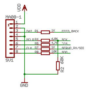
Connectors and pinout Power-In: Flying leads Vin, GND
Power-Out: Flying-leads Vin, SW (open collector)
I/O: Molex Right-Angle PicoBlade socket 8pin (SD53261-0871)
Power-Out: Flying-leads Vin, SW (open collector)
I/O: Molex Right-Angle PicoBlade socket 8pin (SD53261-0871)
PID CONTROLLER GENERAL DESCRIPTION
CONCEPT
The PID-controller is a device capable of regulating the output of the device being controlled to a specific control signal (the wanted value). It is doing so by the following iterative way:
And in even more simple explanation, for example: if the actual temperature is less then the wanted temperature the PID-controller will deliver more power to the connected heating device until a zero difference between the desirable and available values will be achieved.
The PID controller is suitable for controlling and stabilizing many systems e.g.:and more…
The output of the PID-Controller is PWM signal (Pulse-Width-Modulation). It means that by switching the load to the energy source for different amount of times (Pulse width) the average power being delivered to the connected device can be adjusted.
The PID-Controller can read almost any analog or digital signal, and has SPI-bus.
The analog signal can be any 0-5v signal with sensitivity of 5[mV] (10bit resolution)
The digital signal can be any 0-2v / 3-5v signal with selectable timing resolution of 0.5 to 4[uS]
Or minimum Pulse-Repetition-Interval (PRI) of 0.5[mS]
The PID-controller is fully configurable and in certain operation mode can be monitored in real-time during its operation.
For safety reasons, the PID-controller software is equipped with real-time Built-In Test (RT-BIT) to ensure the system is operating in its normal region. The BIT algorithm is as follow:
If the user activates the BIT, any detection of the above events will put the PID-Controller in shutdown mode.
Control-Loop Structure Graphical representation of PID-Controller transfer function
Control-Loop Structure Graphical representation of PID-Controller transfer function
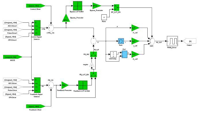
Smart-PID Unique features
Additional to the classic PID control-loop structure, the Smart-PID controller has the following unique features:
Additional to the classic PID control-loop structure, the Smart-PID controller has the following unique features:
Full datasheet can be downloaded from:
http://dl.dropbox.com/u/22843989/Publish/PID_Controller_UG16e.pdf
http://dl.dropbox.com/u/22843989/Publish/PID_Controller_UG16e.pdf
