
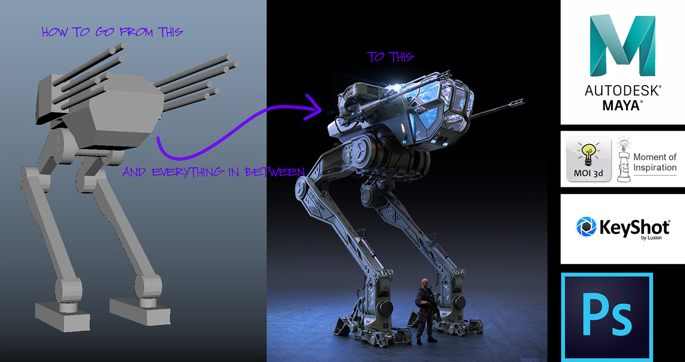
In June 2019 I gave a lecture at the Gnomon School of Visual Effects on the making of for my X-35 Lightning Mechanical Attack Vehicle. If you would like to watch the video you can check it out here. https://www.twitch.tv/videos/442004509?filter=all&sort=time
I designed this mech to be used as a virtual reality experience brought to life by my company Altered Mechanics. We are pairing this up with our Altered Platform simulator to create epic mech battles for location based VR arcades. Due to covid, things have been pushed back a little but we are still moving along to bring these games to life.
Here I am going to share my process for creating this design from scratch. I will explain step by step along with my thought process for my design moves. I hope you enjoy!
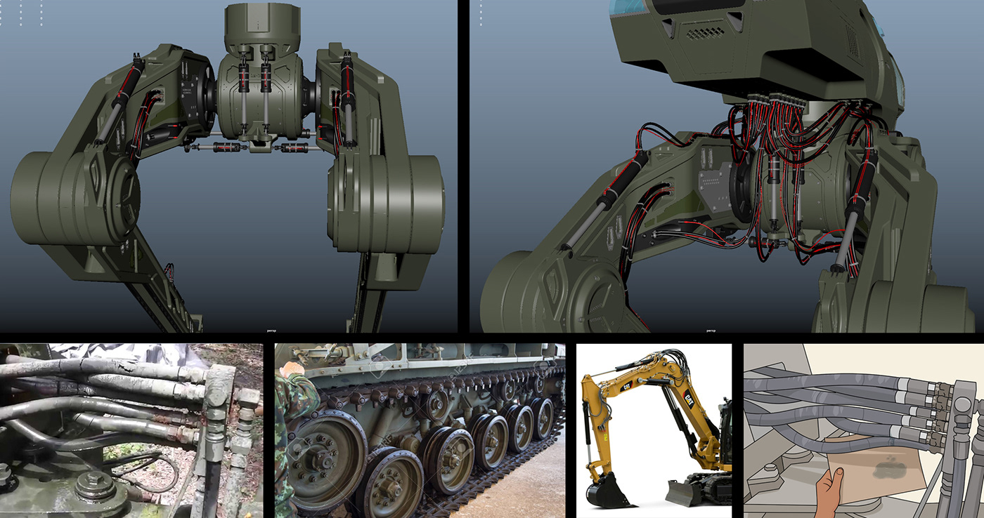
Getting Started - Reference Collection (All reference images were found online and are not my own images)
At the beginning of any design project, I always start by doing an initial reference dive. This phase is not just to find inspiring images, but to also do research on the engineering behind the idea I want to create. Because I am a Concept Designer and not an engineer I have to figure out how to make my final design as real world functional as possible without actually knowing how the engineering will actually work. Luckily there are many amazing real world machines that I can research and study to get a good idea on how to design my fictional project so that appears functional and is believable. I try to mostly reference real world projects and do my best to avoid looking at too many concept designs by other artists. But at the end of the day I usually end up with about 80% real world reference and 20% concept design reference that inspires me.
This first reference collection is just the start. The research phase never ends through out the project. I even use reference when applying materials, choosing my lighting, adding mood to my renders and finishing off my renders in photoshop.

3D Block-in, Stance and Movement - MAYA
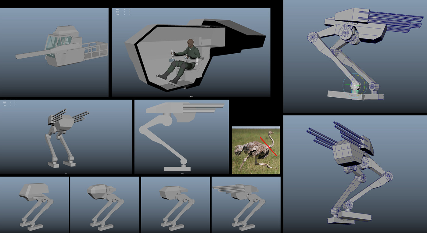
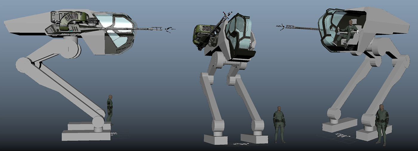
Once the initial research phase is done it is time to start sketching in 3D. In my experience this phase of the project is the hardest part to get going. It is easy to end up staring a blank screen and not knowing where to start. I usually find it very helpful to bring in a few scale figures in different poses and just start building random shapes without thinking much. Just warm up and get in the flow and it will start to come together. In this case I knew there would be a pilot sitting in the cockpit so I just started building around the seated figure and it took off from there. One design move leads to the next and so on.
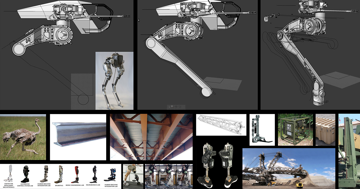
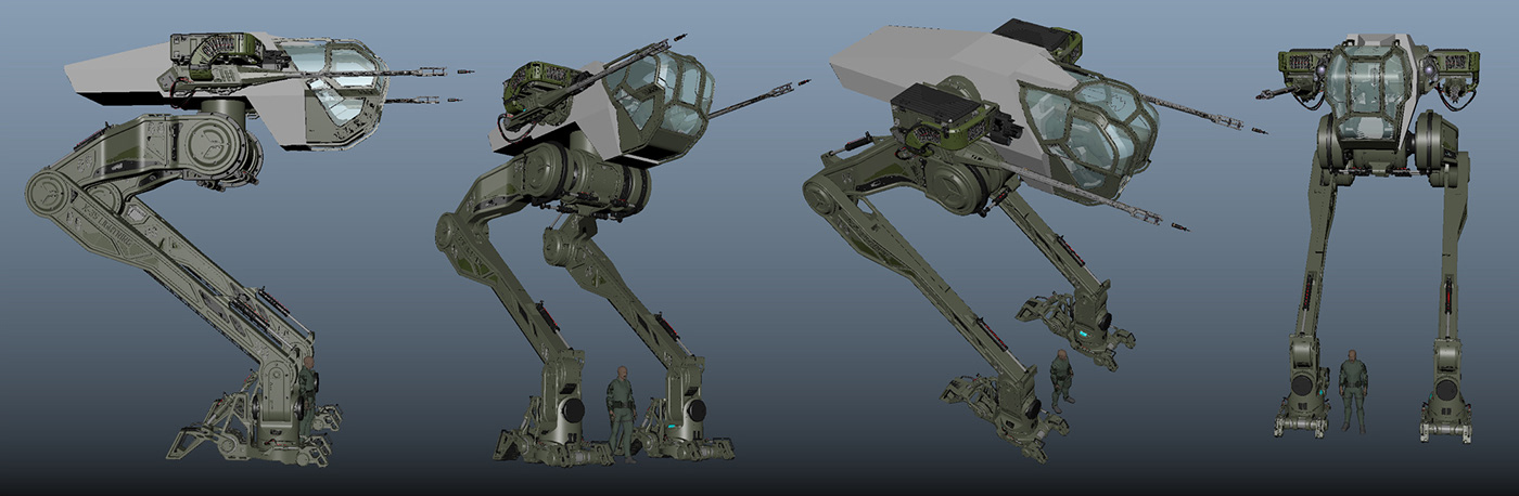
As you can see below, I did a few different cockpit designs quickly to test out shapes and eventually came across something I liked. I also tested out the movement of the different parts of the mech to make sure the joints were in the right place and this thing would move the way I want. I actually missed one joint in the ankle that I later had to add in but I didn't realize it till I looked at that part more closely. Keep your shapes simple and just focus on the overall function. When I was looking at different animals for inspiration I decided I wanted this mech to move like an ostrich because of it's two legs and how fast it runs. The 3D block-in basically became an ostrich with its head chopped off and two cannons attached on either side.
Once the block-in feels good it is time to start breaking the project into mini design parts and tackle them one at a time. But before continuing in 3D, there are a few things that I like to think about and wrap my head around.
Materials
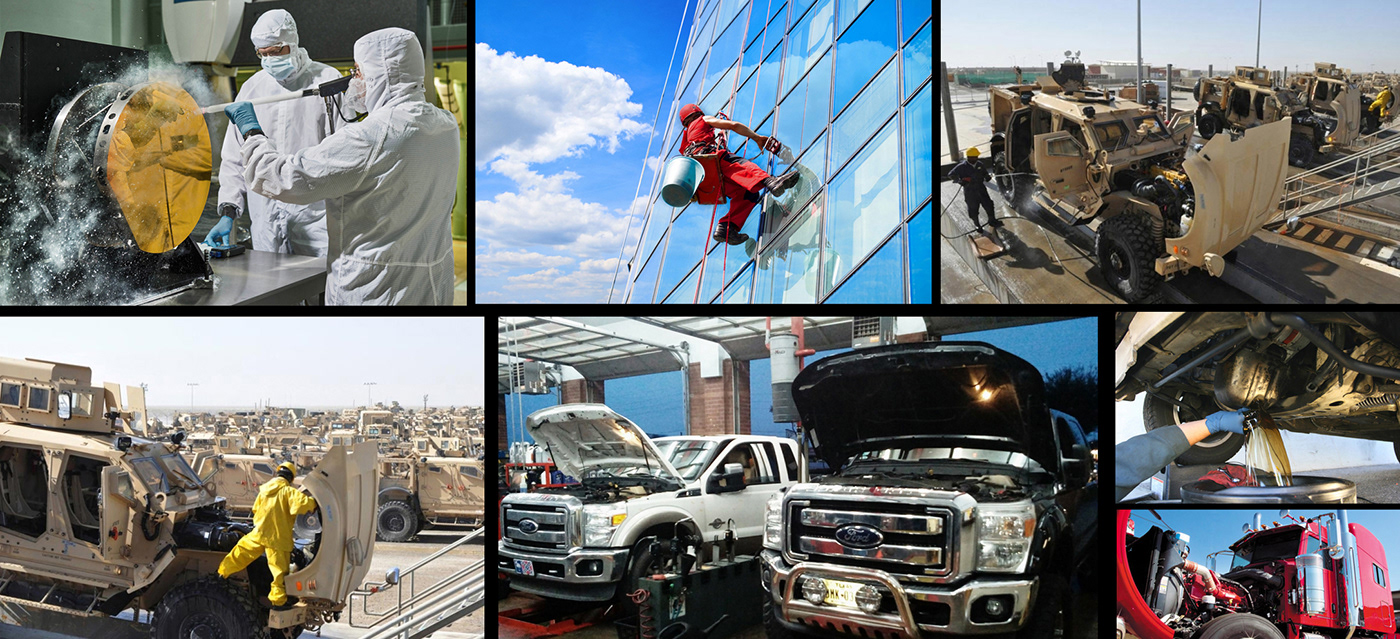
The first thing to consider are materials and what this thing will be made of. I have a pretty good idea on how big this mech will be due to the scale figure that fits in the cockpit. As well I know I need this thing to be strong and sturdy because it is basically a walking and running tank that will be in combat and taking hard hits from other mechs. With this general information I know I want this to be mostly made of steel mixed with carbon that is thick enough to stop large projectiles. You can easily research how tanks are made to get an idea of how the material works and what size sheets it comes in before it is constructed. This info is important because it lets you know roughly where you will have to put cut lines, weld lines and connection joints. This is the same for glass, and all other materials as well.
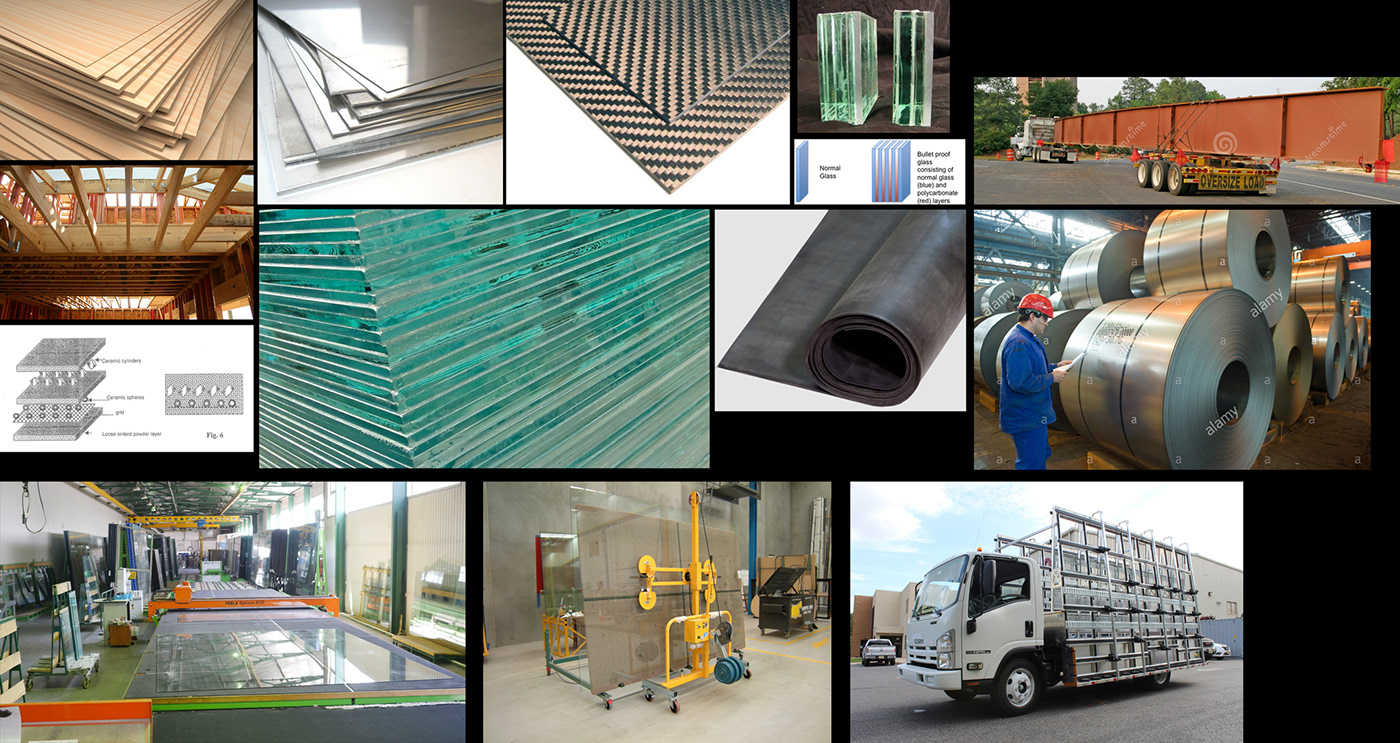
You will also want to think about how the material is going to be transported to the building site where these machines will come to life. If a large truck has to bring countless sheets of steel to a building site, those sheets of steel will be determined by the size of the bed of the truck or train that will take it there. Materials also come in common sizes and when you start to request larger sizes the price will go up drastically in construction costs. Thinking about these things when designing a fictional concept will help you make design moves with a purpose instead of just randomly putting greeble detail where ever you like that doesn't end up making any sense.
Manufacturing
Once you get all of your construction materials to the building site, you are going to also need the proper tools and workspace to build these mechs. You may need to imagine a large warehouse with large tools as the place where this thing is built. The machines used to build the different parts will also start to help you understand how large things can be designed and built and where to put cut lines, joints, connection points, etc...
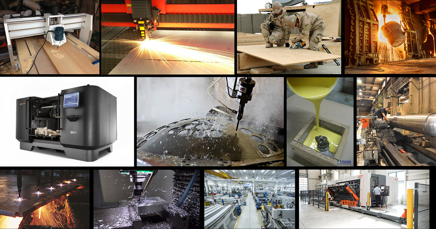
Researching different building technologies and how each different construction technique works will help you understand which design detail should be used and where.
Assembly
Imaging where the mech will be assembled and how many vehicles the military (or similar client) will need, will help the design thought process as well. If the military plans to make thousands of these mechs, then they will most likely be built quickly and cheap. That will give you info on what types of materials and construction techniques they plan to use which will then inform the design decisions and aesthetics of the design. If only a few of these will be built then the materials and construction techniques will be a lot more unique and the overall price will be a lot higher. Decide what the assembly story and purpose of your vehicle is and use that info to help figure out the design with a purpose.
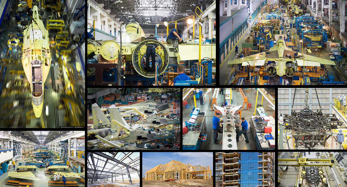
Maintenance
One last thing I like to think about is how will the vehicle be maintained and cleaned. We all like to make really unique and interesting designs, but at the end of the day if we can't fix or clean them they will quickly wear and fall apart. Thinking about cleaning and maintenance will inform how to make design moves that are believable, functional and in the correct place. Places for panels to come off, wires to be replaced, joints to be tightened will all inform the design decision process. At the end of the day your audience won't know every little reason behind each design move you made, but subconsciously they will understand that your design feels right and makes sense to them as something along the lines of realistic.
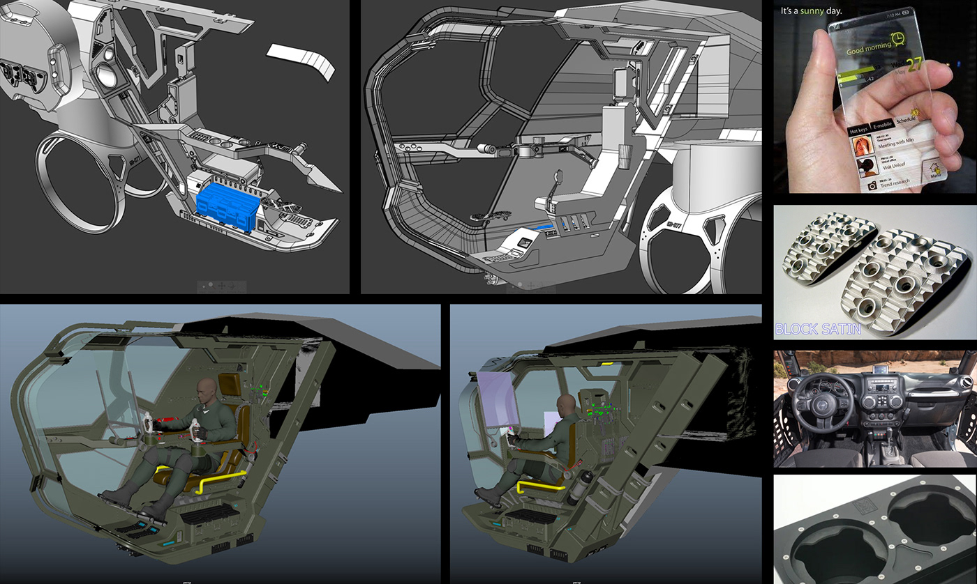
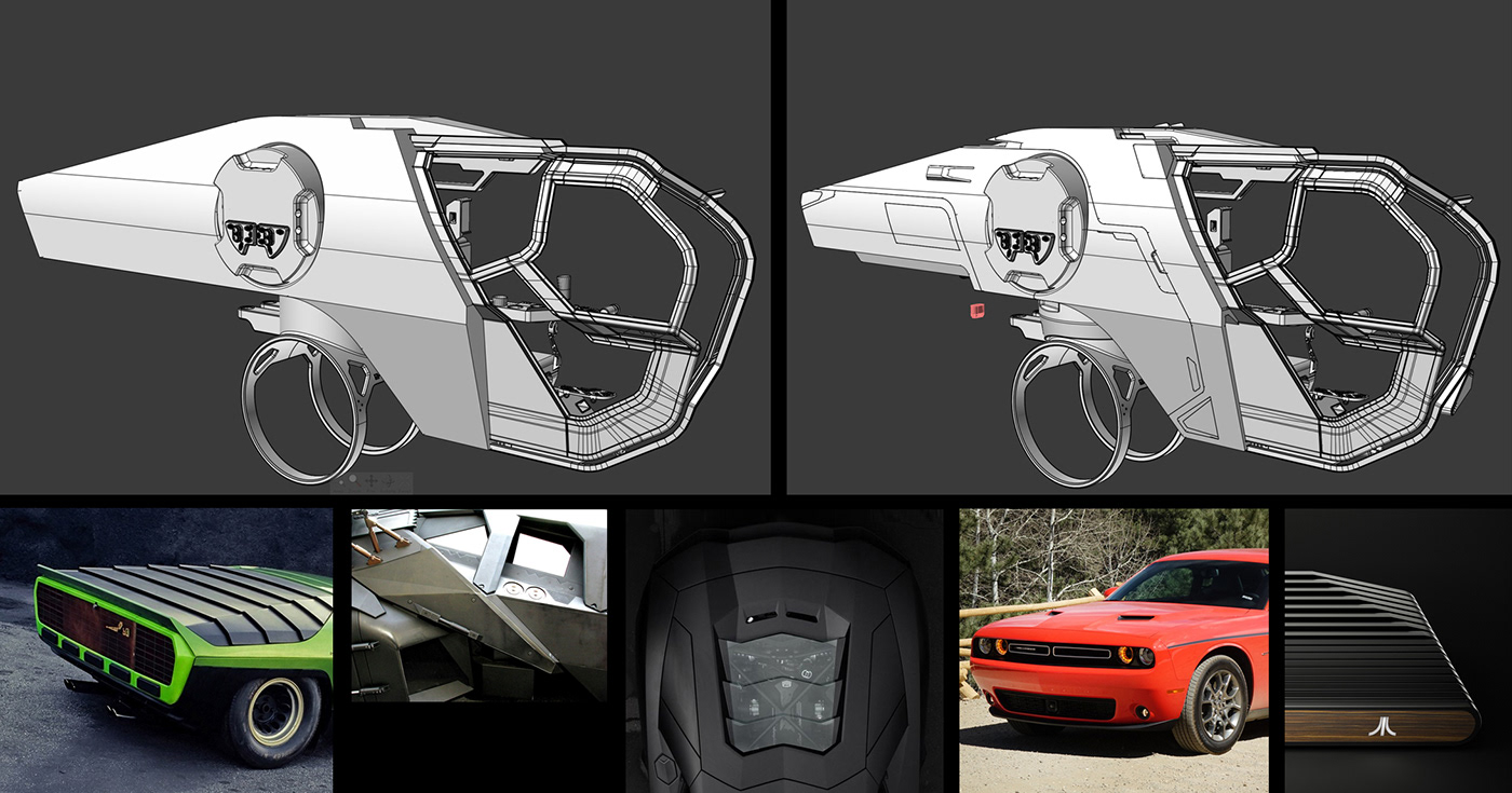
Mini Design Project 01 - Cockpit Exterior
I like to break my large vehicle project into mini projects and figure out each part one at a time. The block-in is like the 3D project outline. I decided to wrap my head around the cockpit exterior first. I chose this mini project because it relates to the human pilot sitting in the cockpit. It is easy for me to imagine how this would come together to protect and allow for visibility for the person operating the machine. I know that the forms need to be strong, and reinforced with extra structural elements for armor. I know the glass areas want to be as open as possible without feeling too weak and exposed. As well, when the mech is going to be built in a warehouse, the body and cockpit will have to be suspended by cranes and held above ground so the legs can be attached on. This informs me of attachment points and other details that will speak to the assembly process of this machine.
Collecting reference images is never ending throughout the design process. Picking the brains of engineers and designers who create real world machines for a living is going to be the best way for me to create believable designs that my audience can relate to.
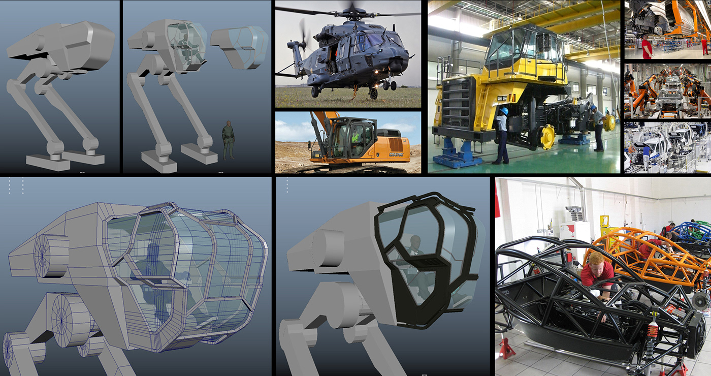
For the cockpit, I chose to use Maya and sub D polygon modeling techniques so I could very carefully control the curvature, highlights and transitions. The canopy class is going to be the main focal point of this design and I want to make sure all the changes between light and shadow are perfectly smooth and flowing.
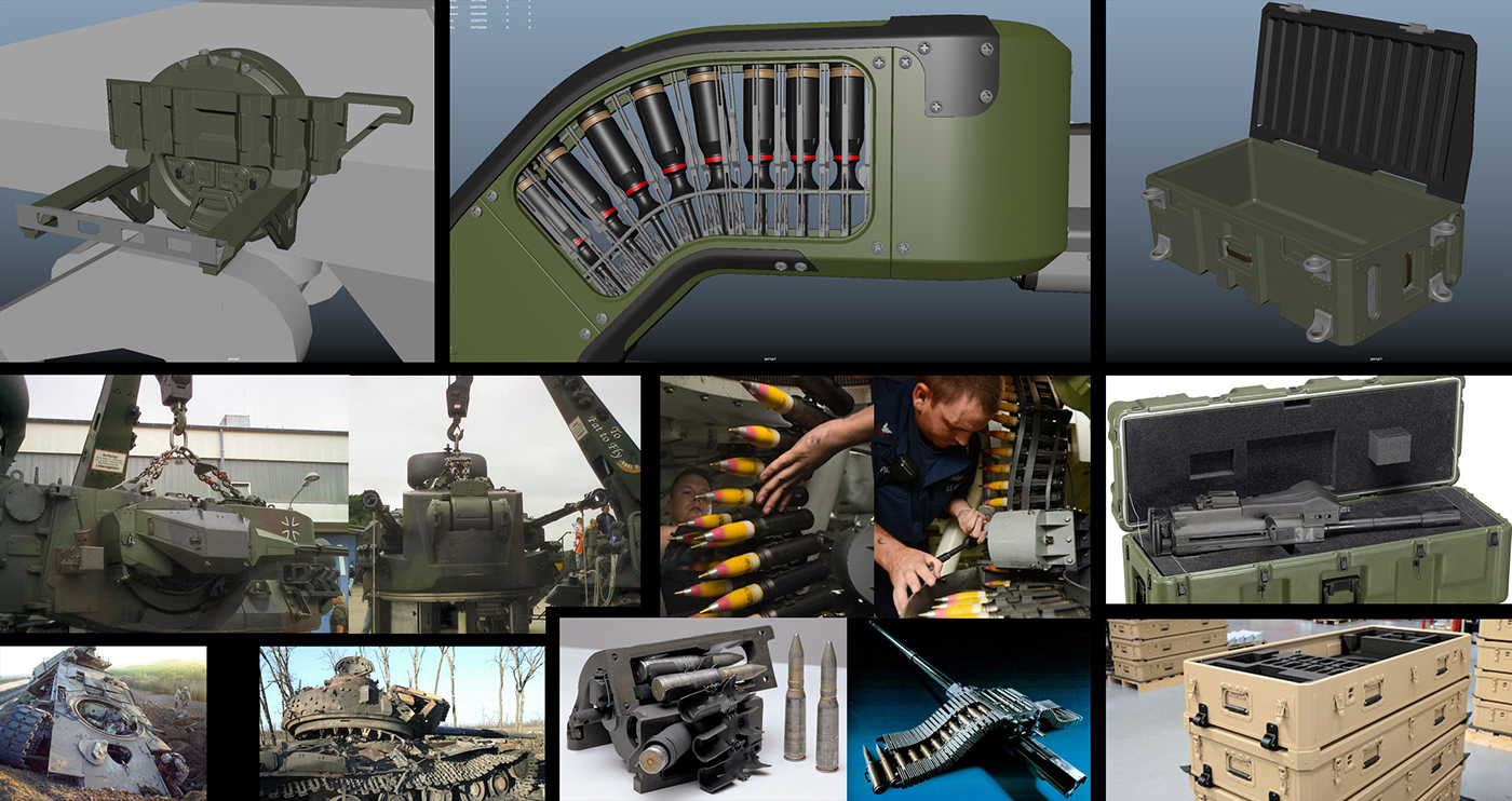
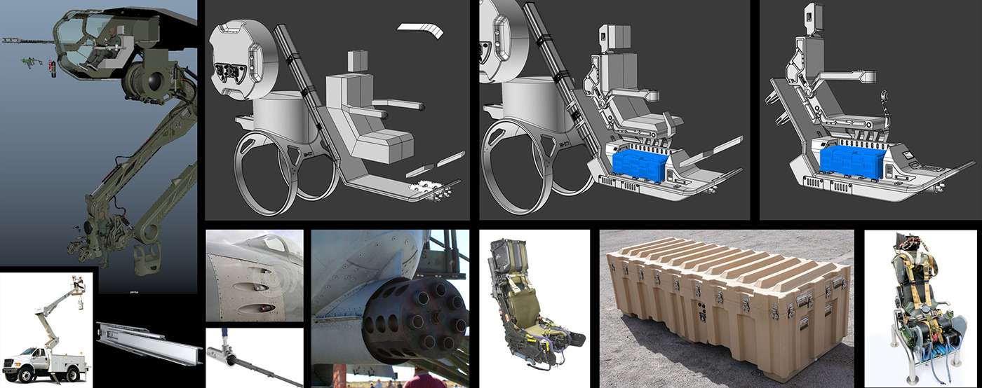
Mini Design Project 02 - Cannon
The second mini project I tackle is the cannon. Once again I have many things to think about when creating this design. Since the mech is so tall, I need to think about how the ammo will be loaded on the gun. I also need to think about how the gun will be attached to the body of the mech. I will need to use a crane for both of these parts so that means a few things. I will need a large container that will hold as much ammunition as possible. The ammo case will need to be loaded on the ground and pulled up into place to be reloaded on the mech. This means the case will need attachment points for chains to hook into it and then easily slide into an attachment point on the gun.
The cannon will need a rotation attachment point on the side of the body for it to move up and down when attached to the body of the mech. The cannon will also need cameras to help with aiming. And the cannon will need to be cleaned and maintained fairly often. The cannon will need attachment points for chains to hook in as well as be able to detach from the rotating pivot point when it is back at the base.
I create the highly detailed cannon design in Moment of Inspiration (Moi3D). I have found that Moi3D is excellent for fast and explorative design. It is easy to quickly test out different ideas and create lots of detail in 3D without having to worry about topology like you would in a polygon modeling program such as Maya. Maya is excellent for certain modeling situations where you really want to control shapes and transitions perfectly and Moi3D is excellent for quick shape and detail ideation. Together I feel like they are extremely powerful and allow me to create anything I like.
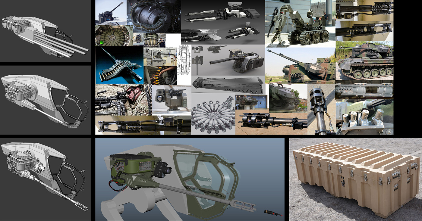
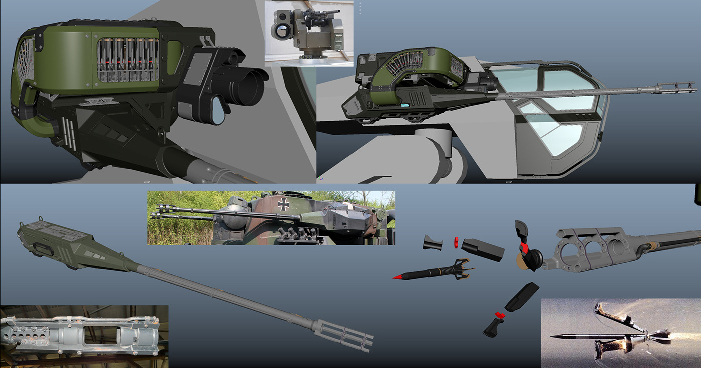
Once the cannon mini design project is complete, I replace the simple block-in part on the overall mech and slowly watch the design come to life.
Mini Design Project 03 - Leg
Next up is the leg. The hardest part here is to figure out how the joints need to move in order for this thing to walk, run and stand on uneven ground. Researching how humans and animals move and understanding ankles, knees, shoulders, elbows and so on is very important. I have seen (and accidently designed my own) stiff mechs that won't work at all because they don't have the correct joints and movement direction for the moving parts. It is very important to get these details correct otherwise the design will be nothing more than and pretty looking useless object. Start by simply laying out the joint rotation points and testing out the maximum movement each joint will give you before diving into detailing the parts out. I can not stress enough how important this part of mech design is. Do as much research as possible!
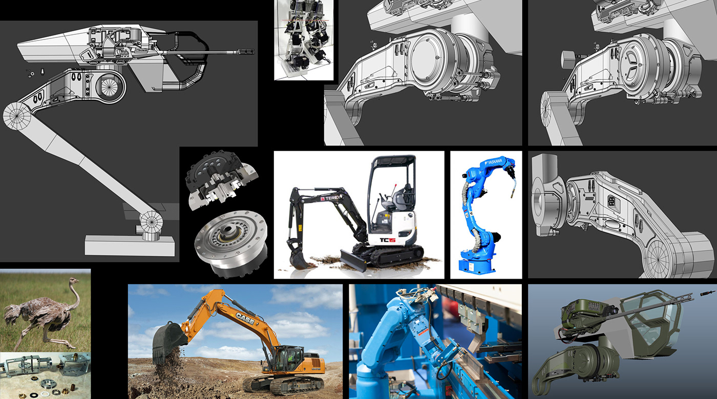
As well as figuring out the movement, think about the strength of the materials and how to use different shapes that speak to lightening up the weight of the part while keeping it strong. Research structures like trusses, I beams and more that span long distances while being strong and light and use that info to help design your parts.
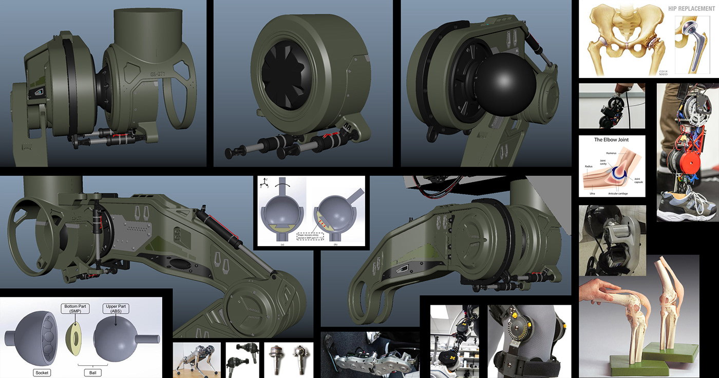
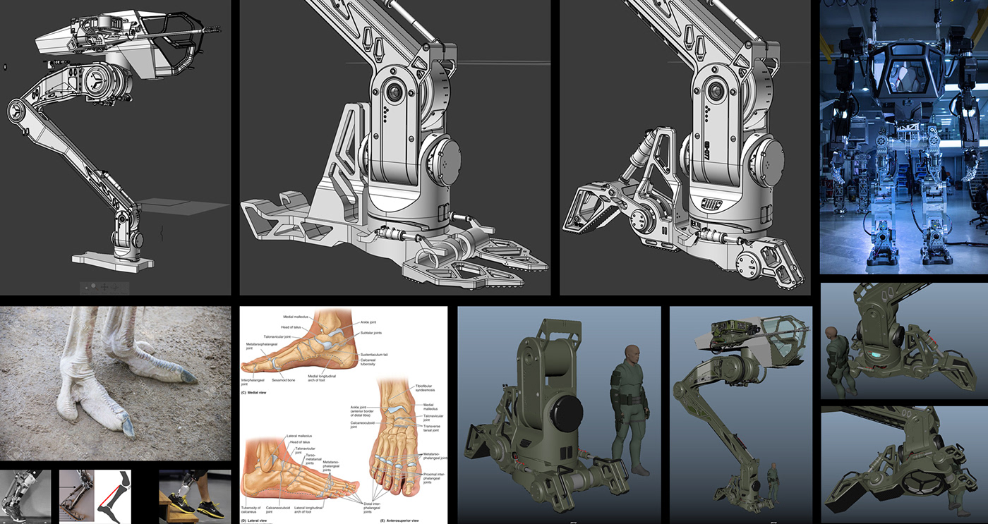
Mini Design Project 04 - Foot
Next mini project is the foot. The movement in the ankle is quite complex and needs a bit of research. Look at how different animal and human ankles and feet work to understand what joints you will need. If you look at your own ankle, there are many different ways you can rotate your foot but also there are plenty of points where the rotation stops. Use this info to design points where rotations stop in your mech by creating points where one piece doesn't allow the other to move past a certain angle. When I initially blocked-in the rotation points for the foot of this mech I missed a very important side to side movement. Luckily the Method 1 manned robot project by Korea Future Technology which was concept designed by Vitaly Bulgarov shows how a mech of this size and weight moves. Watch the video in the link above shows how important the side to side movement is when something like this walks. I had to adjust how the joints I had initially laid out work and fix my design as I go into the detailing of the foot.
As you can see, I initially had gone one direction in the design and I didn't like it, so I had to self Art Direct and change it up till I got something I liked.
Mini Design Project 05 - Cockpit Interior
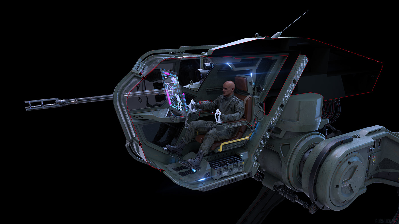
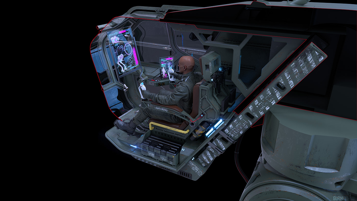
The cockpit is super fun to design. Because there are so many human interaction points with this area of the vehicle, it is fairly easy to make functional decisions that your audience will relate to. Things like chairs, places to put your feet, touch screens, buttons, etc... fill the space and bring everything together. The large cannons on the mech are used in mech to mech combat, but I also decided that I needed some more close range mech to human combat weapons. So I added a Gatling gun that goes underneath the seat and two ammunition containers holding 1200 rounds on each side of the seat on the interior. These containers will be reloaded when the mech is back at home base and the pilot exits the mech. Since the mech stands so high, the interior seat needs to telescope down for the pilot to get in and out, so I need to work that into my design as well.
Mini Design Project 06 - Body
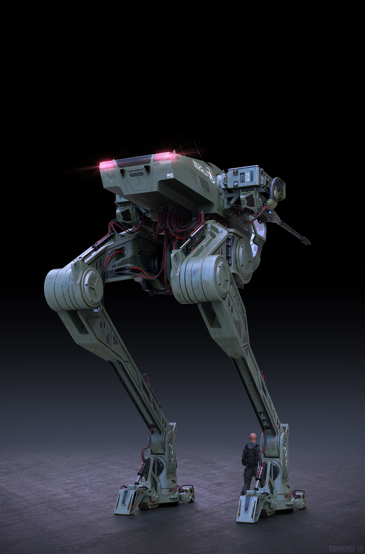
The last part of the project to design is the body of the mech. This part is going to encase the power source that allows the vehicle to move. I have to design access panels that can open, to reach mechanical parts inside, as well as consider the size of the materials used to build the body and manufacturing techniques to bring it all together. I search similar real world projects to get an idea of how to allow for airflow for cooling of internal parts and exhaust to escape where necessary. I didn't end up designing what goes behind the external shell, but I am imagining what would be behind there and using that story to make design moves on the exterior. Every design move has a functional reason for it.
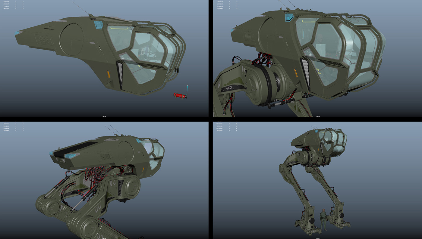
Lastly I add all the wires and cables that power the legs and feet. I purposely leave these exposed as I do want there to be a little vulnerability to this walking tank. Similar to a regular tank where if the tread breaks the tank is stuck and needs repair. In this case if a soldier sneaks up on the mech, it can try to cut the power cables on the feet or legs or use a rocket launcher to destroy the main area where the cables plug into the power supply underneath in the back, to take this mech down. A soldier can also try to blow up one leg to stop this mech from working, but the legs are tall and skinny so properly aiming at them to cause enough damage is tough. It won't be easy to do, but it is also not impossible.
Rendering - Keyshot
Now that all the 3D design is complete it is time to start rendering. I always bring everything back into Maya to bring the whole project back together. If the files get too heavy I have to break them up into a few different files (5 different files for this project). I set up temporary materials using Blinns and Lamberts to decide which parts will take matte green paint, steel, rubber, etc... Next I send the 3D files to Keyshot and start replacing the temporary materials with realistic materials from the keyshot library. I play around with labels, lighting and camera angels and start creating different render passes.
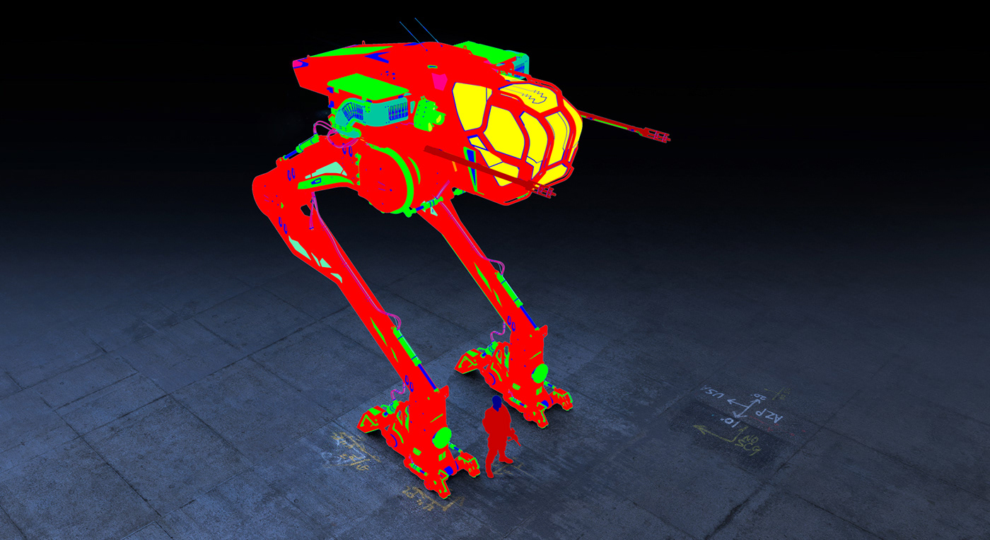
Render passes:
Base Materials
Materials with Labes
Raw steel
Rust
Clown
Ambient Occlusion
Curvature
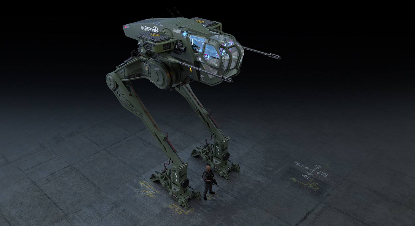


Next I bring these render passes into photoshop and start comping them together to bring the render to life and tell a story of how this vehicle is used. I add weather and wear with scratches and dirt, add glow to the lights and overall bring a soul to the image to help tell the story of this design.
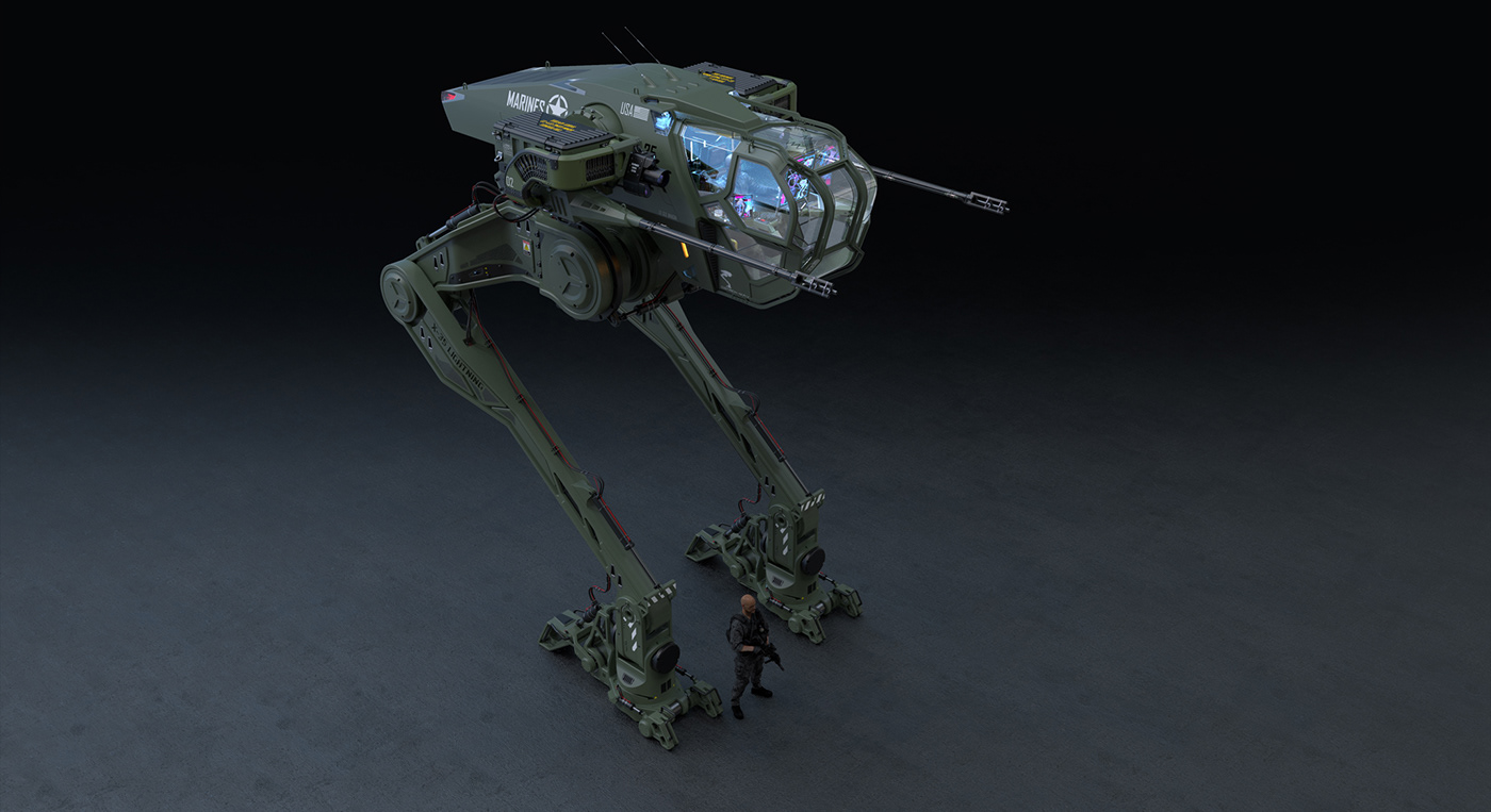
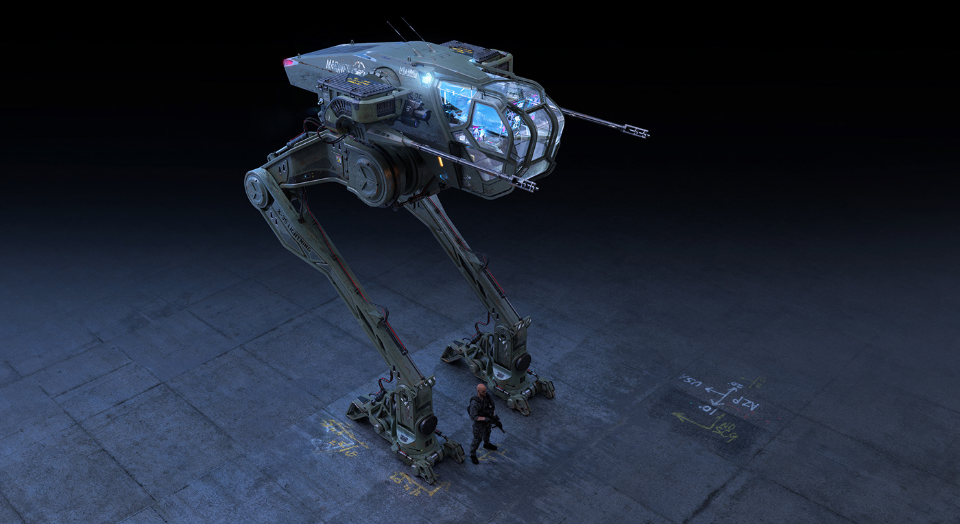
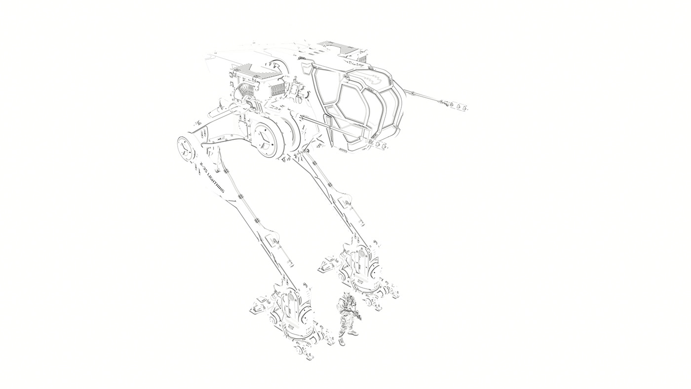
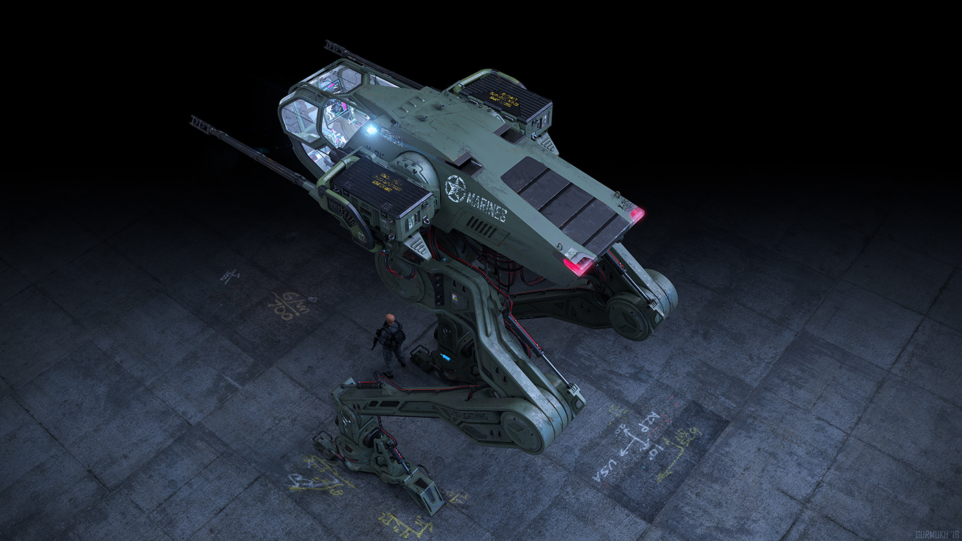
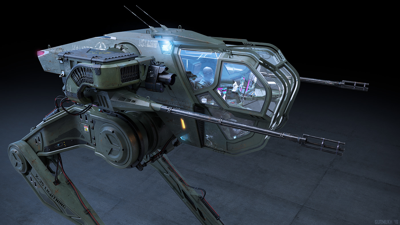
Finally the design is complete! Since this vehicle is designed in 3D, I am able to render out multiple views and show off every little part I have created. Eventually I will create some illustrated action type renders of this design, but for now I just have interior and exterior renders.


Thanks so much for reading this making of article. I hope you enjoyed it! Please let me know what you think and if you have any questions.


