These are some details, diagrams, and photos of a networked camera prototype I built with Arjuna Baratham while at engineering school back in 2009. The project features a digital camera that can be connected to a network and controlled remotely by another prototype to perform image processing and picture transfer using hardware compression.
Arjuna and I developed the project as an embedded system using a FPGA chip (NIOS II), Verilog, and C. We used two Altera DE2 Development Boards, a small OEM digital camera module, a computer monitor, and Altera CAD Quartus II software to implement our hardware design in the FPGA.
The project worked as a set of two prototypes. The first one used a DE2 board with a camera module, and connected via network (Ethernet) to be controlled with commands sent by a second prototype. When the first board (prototype) received a command to take a picture, it communicated with the camera module to snap and retrieve an image from the camera sensor. Then the system stored the picture in external SDRAM and waited for other commands to perform image processing such as time-stamping over the image, and y-axis mirroring. When the second board sent a command to request the image, the first board compressed it rapidly by using hardware and sent the compressed image over network. The second board received the picture, decompressed it (using software), and displayed it to a monitor via VGA port.

System diagram of the project. The system software runs as an FPGA application on the core along with the hardware compression module in the form of a three-component circuit module that takes continuous 8-bit data stream segments and produces encoded 24-bit data stream segments. The RLE unit uses a state machine to process the image data stream using run-length encoding, a simple form of lossless data compression. (Diagram: Randy Balbuena)

Project prototype featuring a DE2 Board using a NIOS II 32-bit softcore (largest chip near the center) and a small OEM digital camera module (top right). (Photo: Randy Balbuena)
First, we built the hardware piece for our embedded system using the Altera Quartus' IDE and SOPC Builder (System On a Programmable Chip) to generate the Verilog that was written for the processor. We also defined interrupts for our design and a PIO interface for our own hardware compression module. The module features three hardware components: an 8-bit input FIFO (first-in-first-out) queue, a RLE (run length encoder) unit, and a 24-bit output FIFO. We wrote these components in Verilog and integrate them into the main design. Once our hardware design specification was complete, we synthesized the Verilog code down to the processor’s lookup tables, and burned to the NIOS chip.

RTL View of the RLE encoder hardware pieces RLE encoder connecting to each other and with the NIOS processor. The new circuit modules and ports/interface were added to the NIOS core. (Screenshot: Randy Balbuena)
As a last step we created software in C to activate the hardware through NIOS/Eclipse. We wrote software for all the serial communications with the camera module following the data protocol specification from the manufacturer's datasheets. We also developed software for all the 2-D image manipulation and effects, and routines that make use of the RLE compression module.

I wrote this simple function in C to compress the picture. It makes use of the hardware compression module created during the hardware design phase. Basically, the function takes a binary string (picture data), pushes the data into the encoder's hardware (via the interface/ports), and gets it out, while the hardware module takes care of the actual compression work. This results in a very rapid compression; many times faster than using software alone. (Screenshot: Randy Balbuena)

Above a byte-level representation of the communication format to connect the two prototypes following the 5-layer Internet model for networking. Commands, messages, and the picture data are encapsulated into an Ethernet message before transmitting them over the network cable. If the message ("Msg." at byte 47) is a picture then it will be in compressed format. (Illustration: Randy Balbuena)
We implemented layers 2 through 5 in the UDP/IP (IPv4) stack model by developing code as a C library we named "networking.h." We wrote routines in the library that help us encapsulate the send data into the different layers as follows:
• Creation of an Application Layer (5) message specifying the actual data exchange between the prototypes.
• Encapsulation of the message into segment at the Transport Layer (4).
• Encapsulation of the segment in a datagram at the Network Layer (3).
• Encapsulation of the datagram in a frame at the Link Layer (2).
• Sending of the frame over the Physical Layer (1) via the Ethernet controller.
We also developed routines to unpack the receiving data, and to compute and validate different types of checksums within the frame.
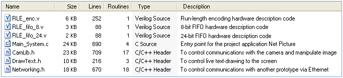
This is the main list of files written for the project; more than 2700 lines of code to create the FPGA hardware (in Verilog) and the system software (in C). (Image: Randy Balbuena)

Picture of the two prototypes as DE2 boards connected via Ethernet network. The board at left sends commands to the board at right, which connects to the camera and has image manipulation and hardware compression functions. (Photo: Randy Balbuena)

A photo of me taken from the monitor connected to one of the prototypes. First, the picture was taken from the camera sensor, downgraded two tones, compressed in hardware, transmitted over the network to the other to the other prototype, decompressed with software, and displayed to the monitor. We were able to achieve a compression ratio of 38:1 with that sample picture and the current algorithm (see ratio on the top left corner). (Photo: Randy Balbuena)

