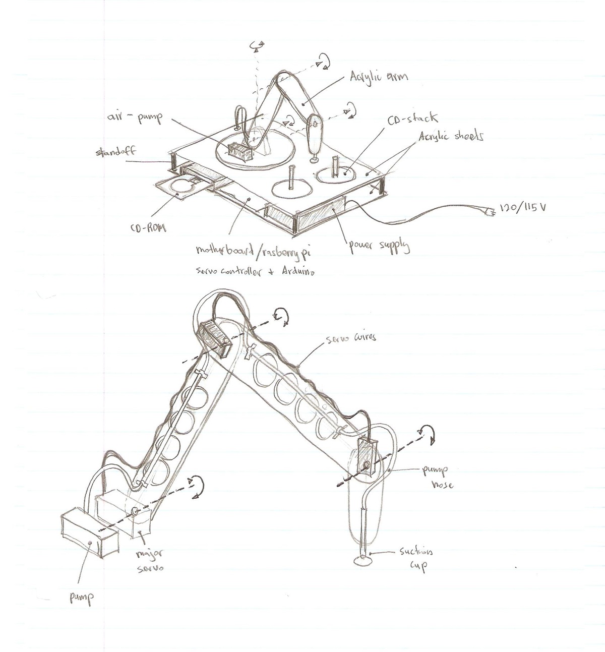
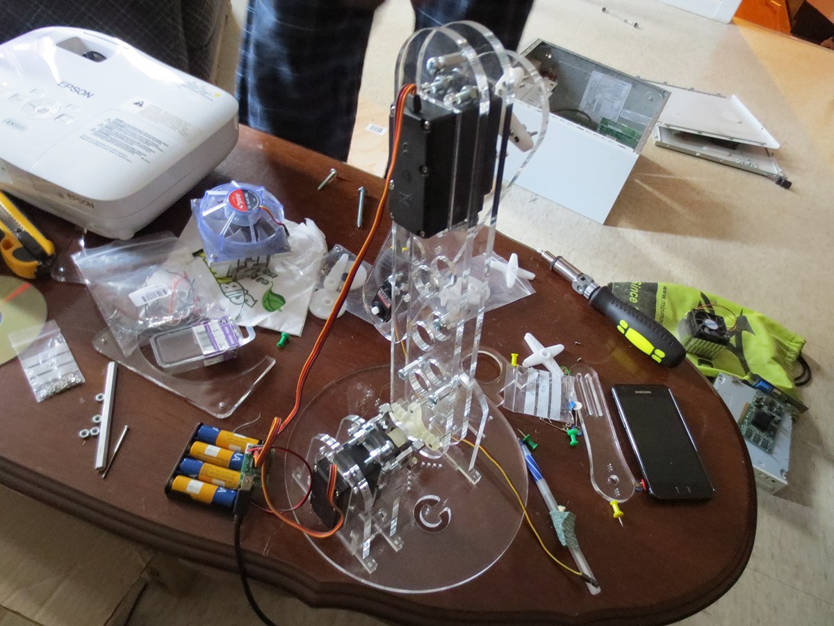
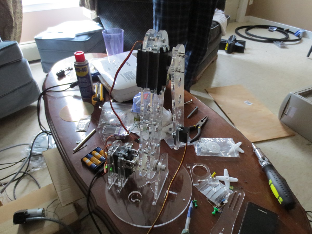
Initial design of the Robot, basic layout containing degrees of freedom, placement of the servos, wiring and accounting for the slack needed to allow the arms to operate freely and without resistance.
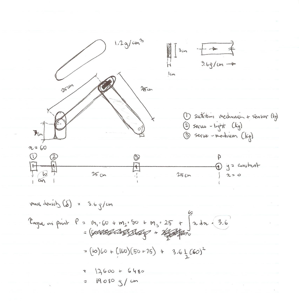
Torque calculations to avoid servo-stalling and over-current in the device. The worst case scenario on the main servo is a torque of 19 kg/cm, from this we decided to use a 20 kg/cm torque handling servo.
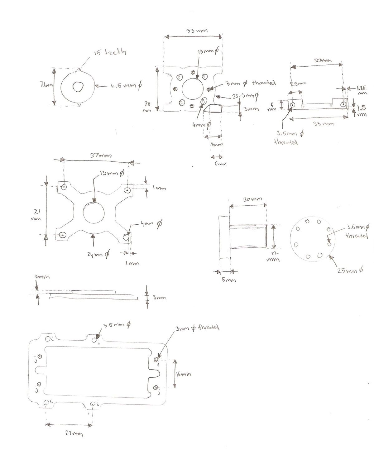
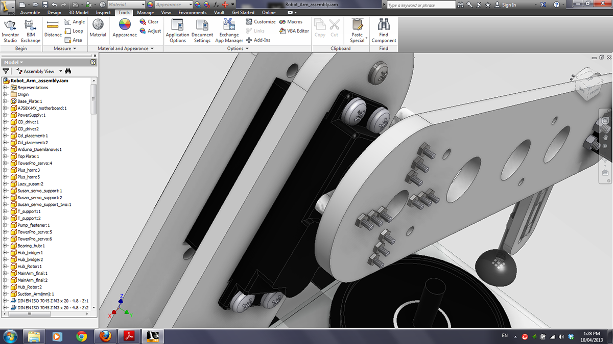
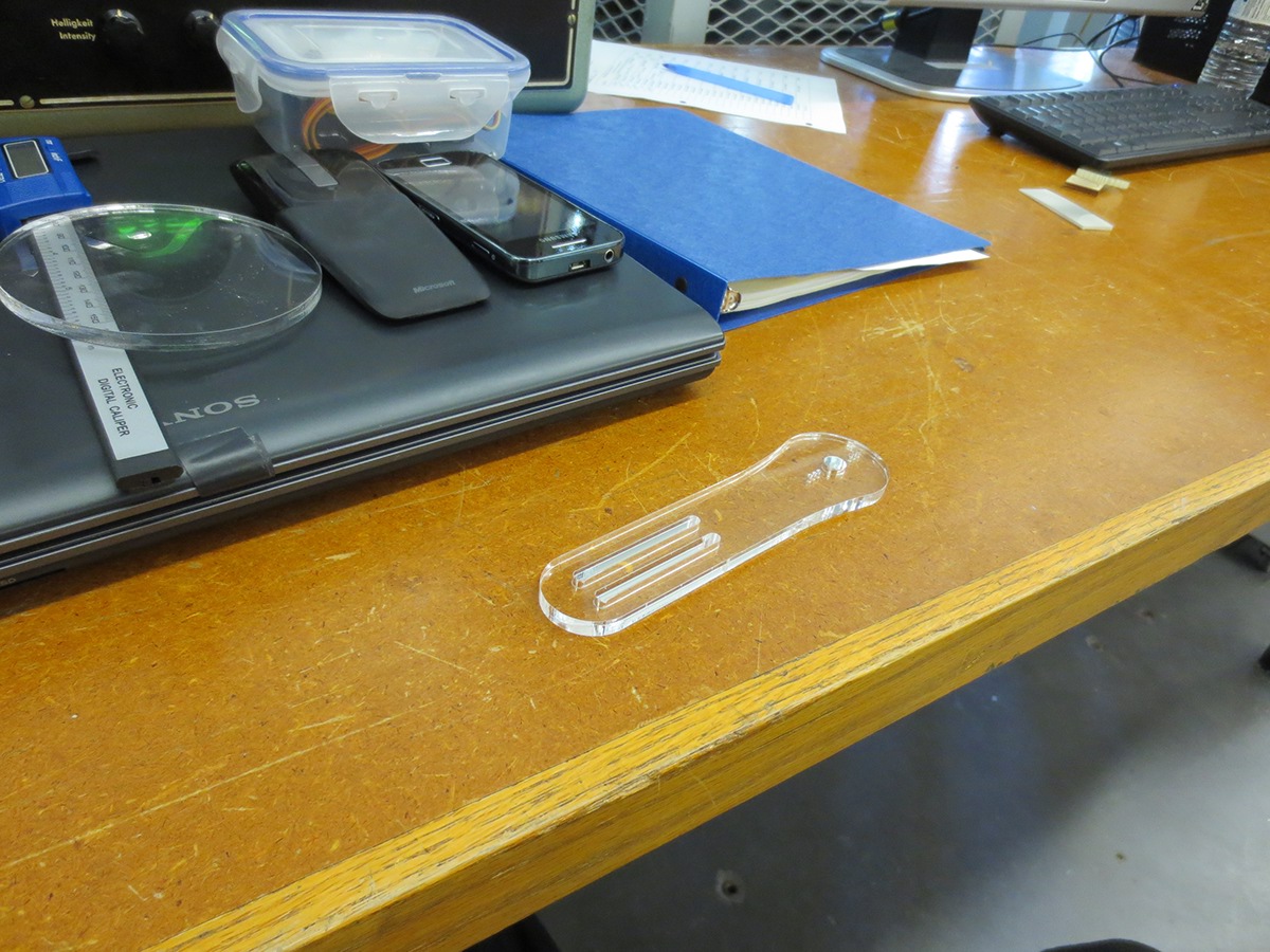
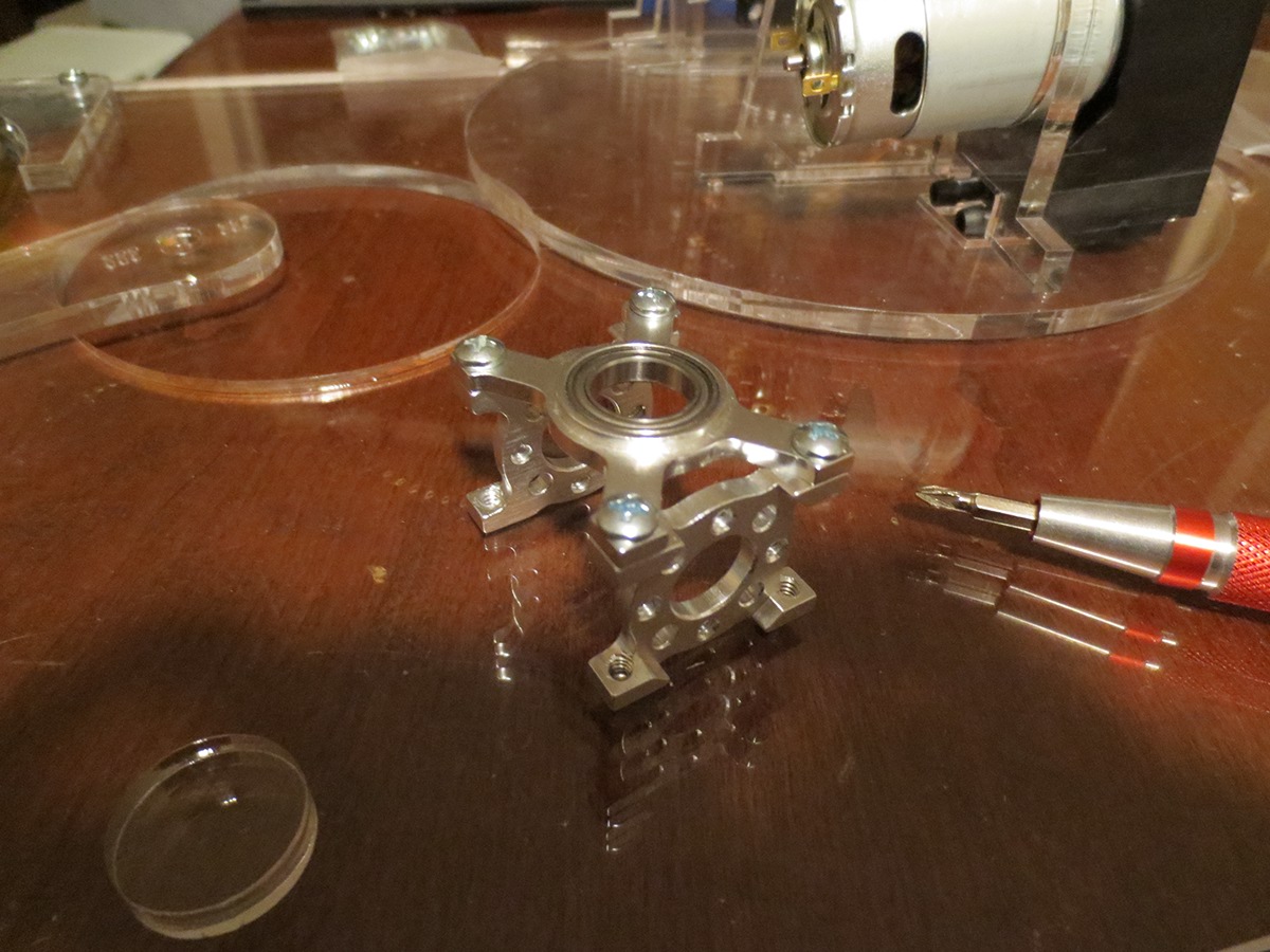
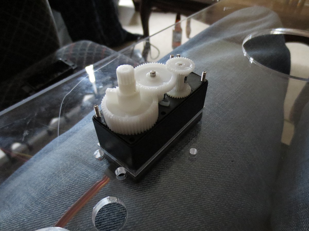
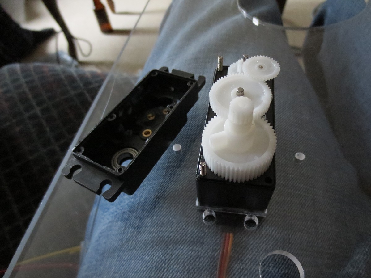
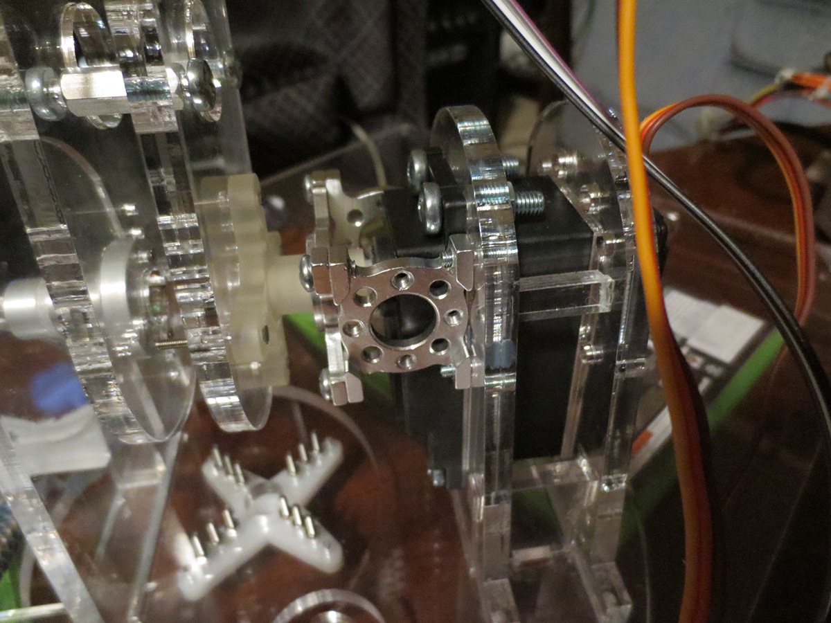
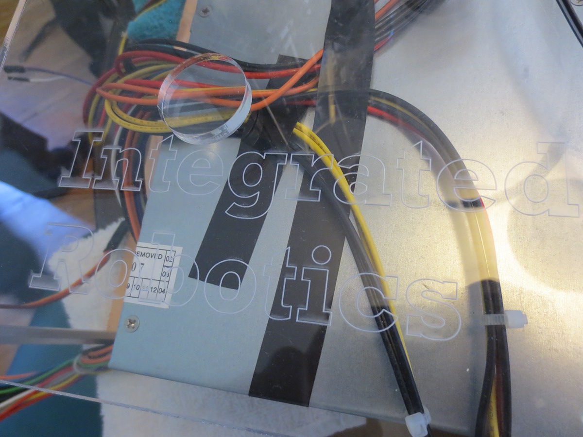
Dimensional notes taken on the Aluminum-grade servo hub prior to start of implementing the design onto Acrylic sheets. The servo hub helps redirect most of the lateral-applied stress from the arm away from the spline of the servo, this ensures that the servo can operate safely and reduces the need for calibration on the software side.
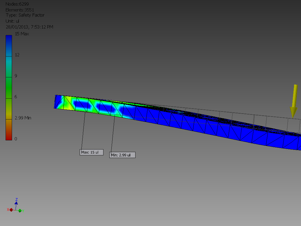
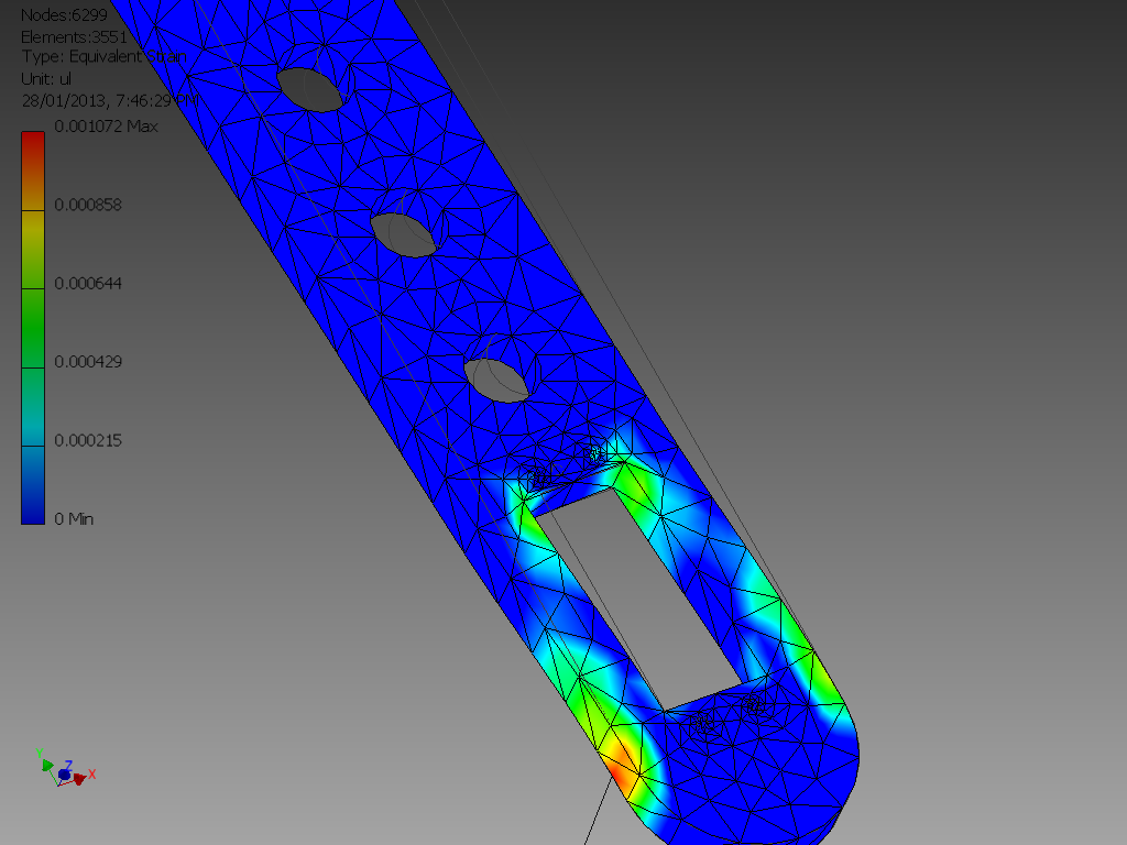
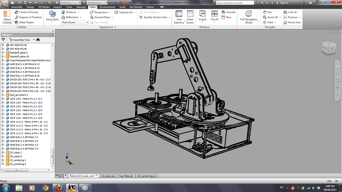
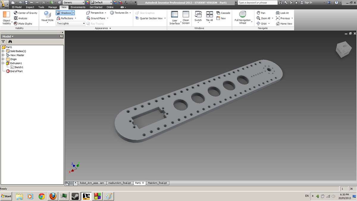
Stress Analysis using Autodesk Inventor's integrated FEA system. Multiple arm designs were created by the team, and were all tested for their weak points, slight changes were made to the most successful arm and then tested again. The arm shown above passed all our tests and is the design that we have decided to implement into our robot.
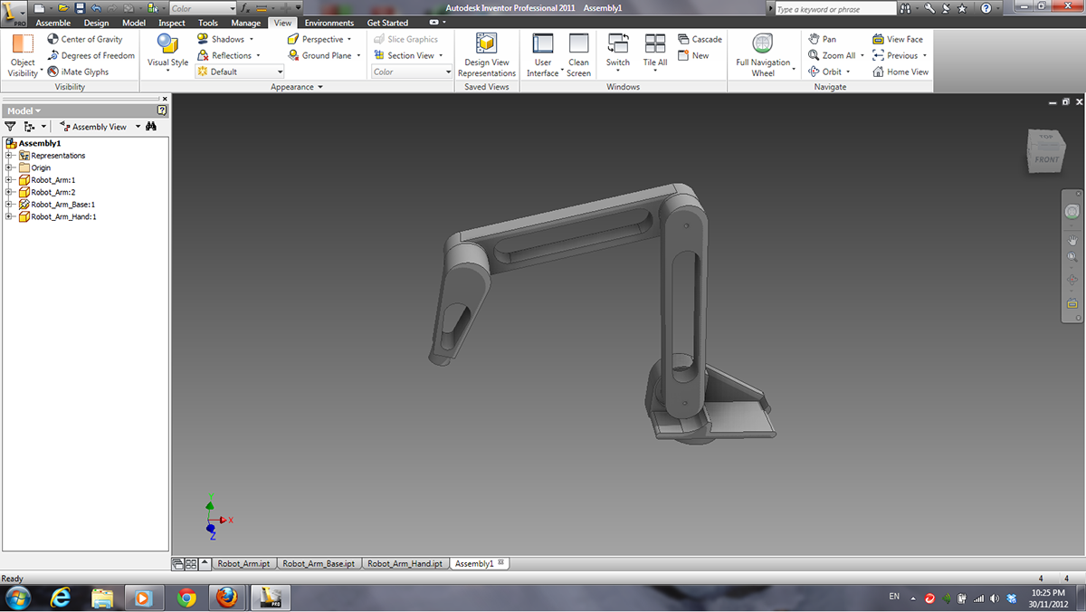
The original simple design excluded any real life factors such as the method of fastening joints, application of movement, manufacturing process, Stress Analysis, appearance and many others. This design was used solely as a template for our newer designs and was also used as a model in OpenGL as we were developing the software that implemented the C.H.O.M.P. algorithm.
The original path (line of red dots) goes from point A to B in a linear fashion and intersecting the cylinder. The CHOMP Algorithm is applied to the path multiple times until it produces a short path which avoids contact with the environment.
More information on CHOMP can be found here:
http://repository.cmu.edu/cgi/viewcontent.cgi?article=1040&context=robotics
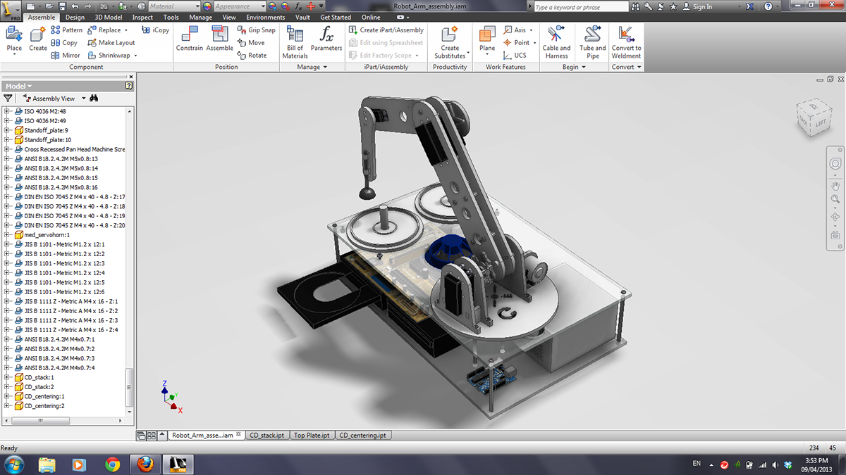
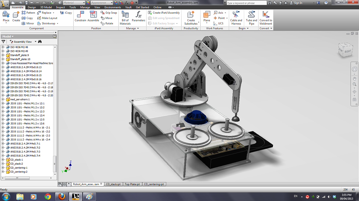
The final design works on the basis of a simple manufacturing and assembling process, this allows us to spend a greater deal of our efforts on calibrating and implementing more sophisticated code in the future and to include object recognition, spatial modelling, voice programed actuation and any other interesting but plausible ideas which we would come across and be interested in trying out.
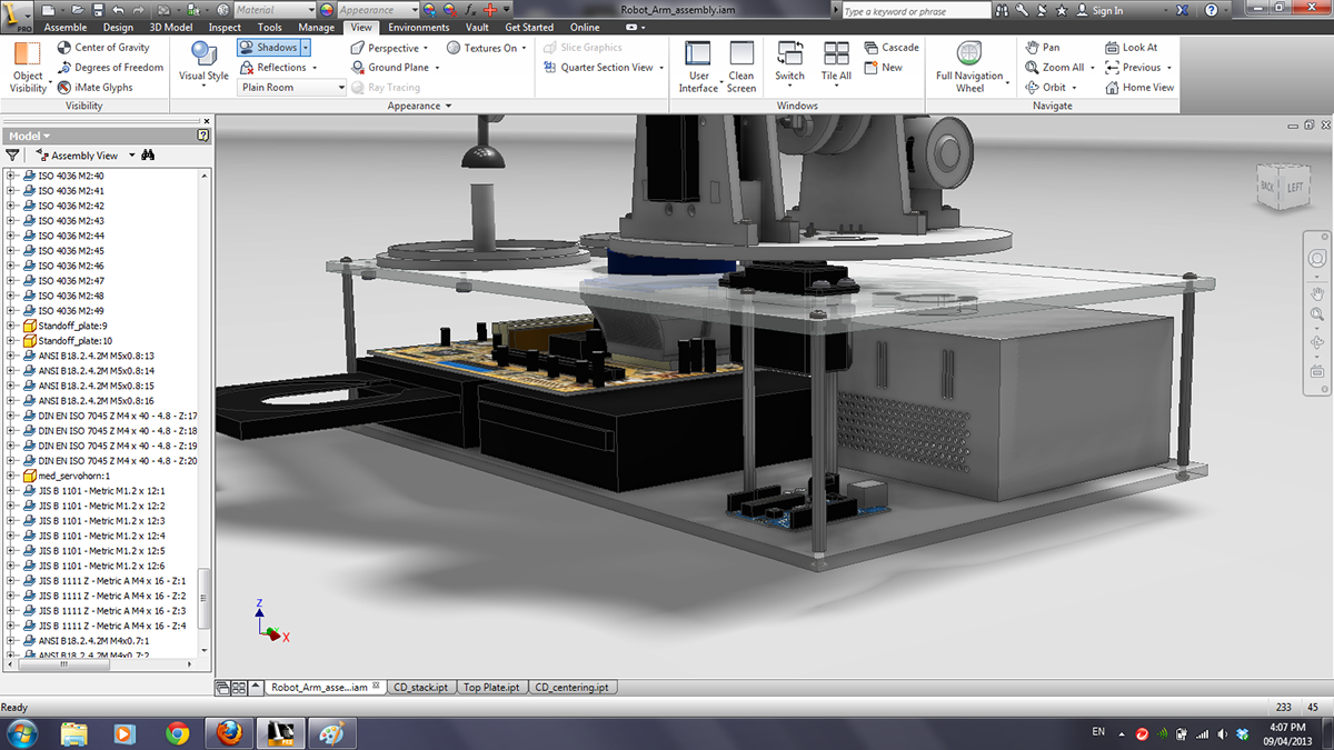
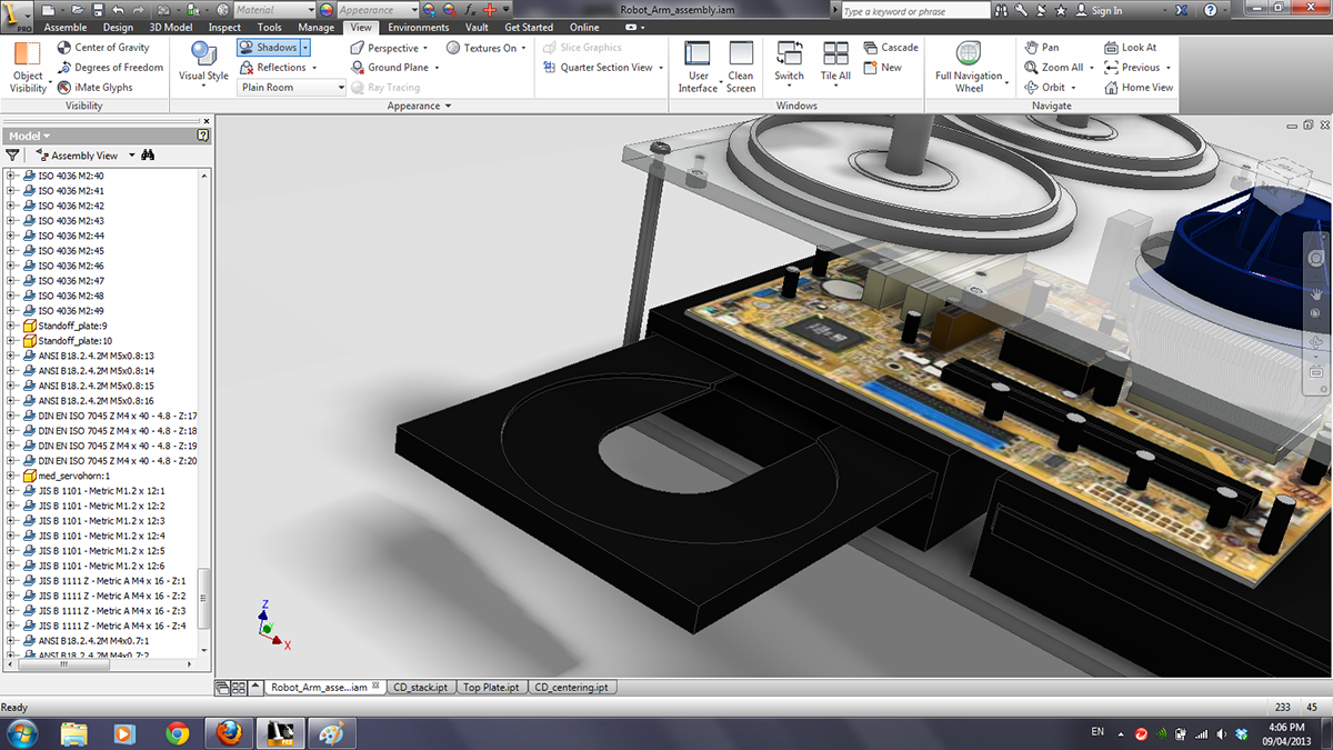

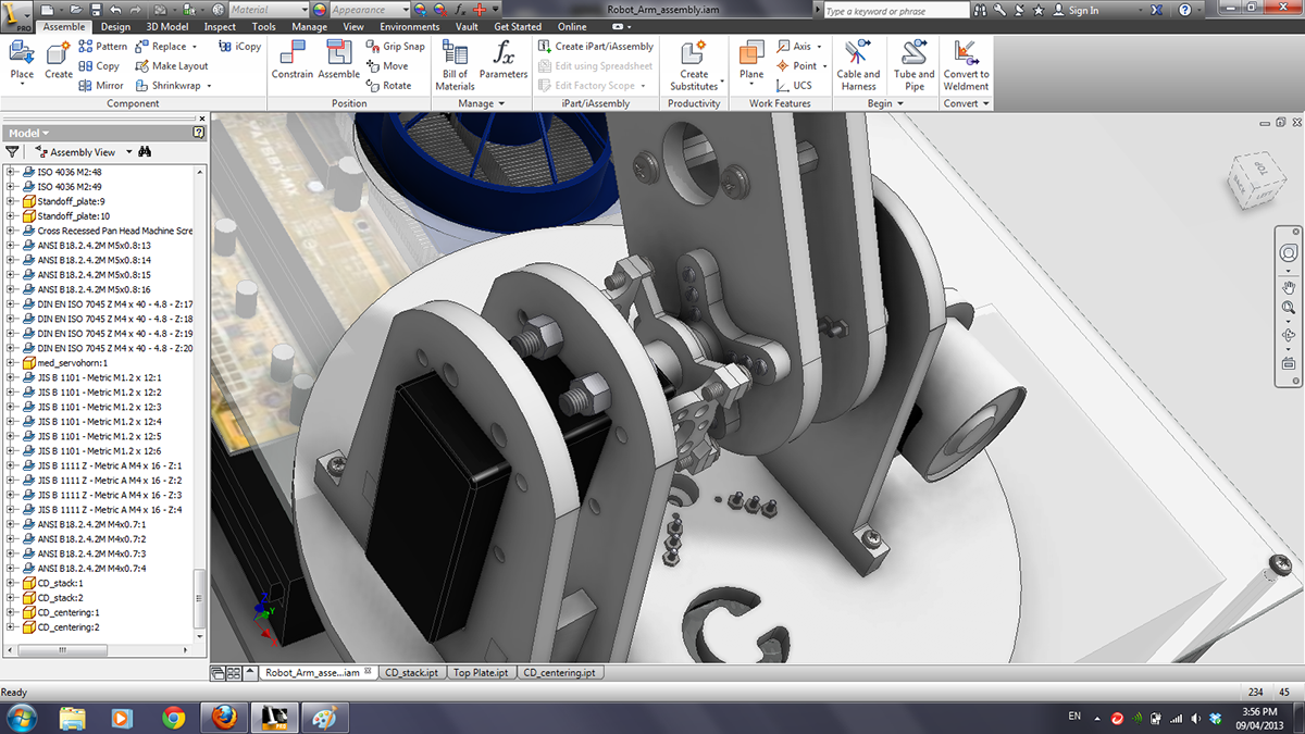
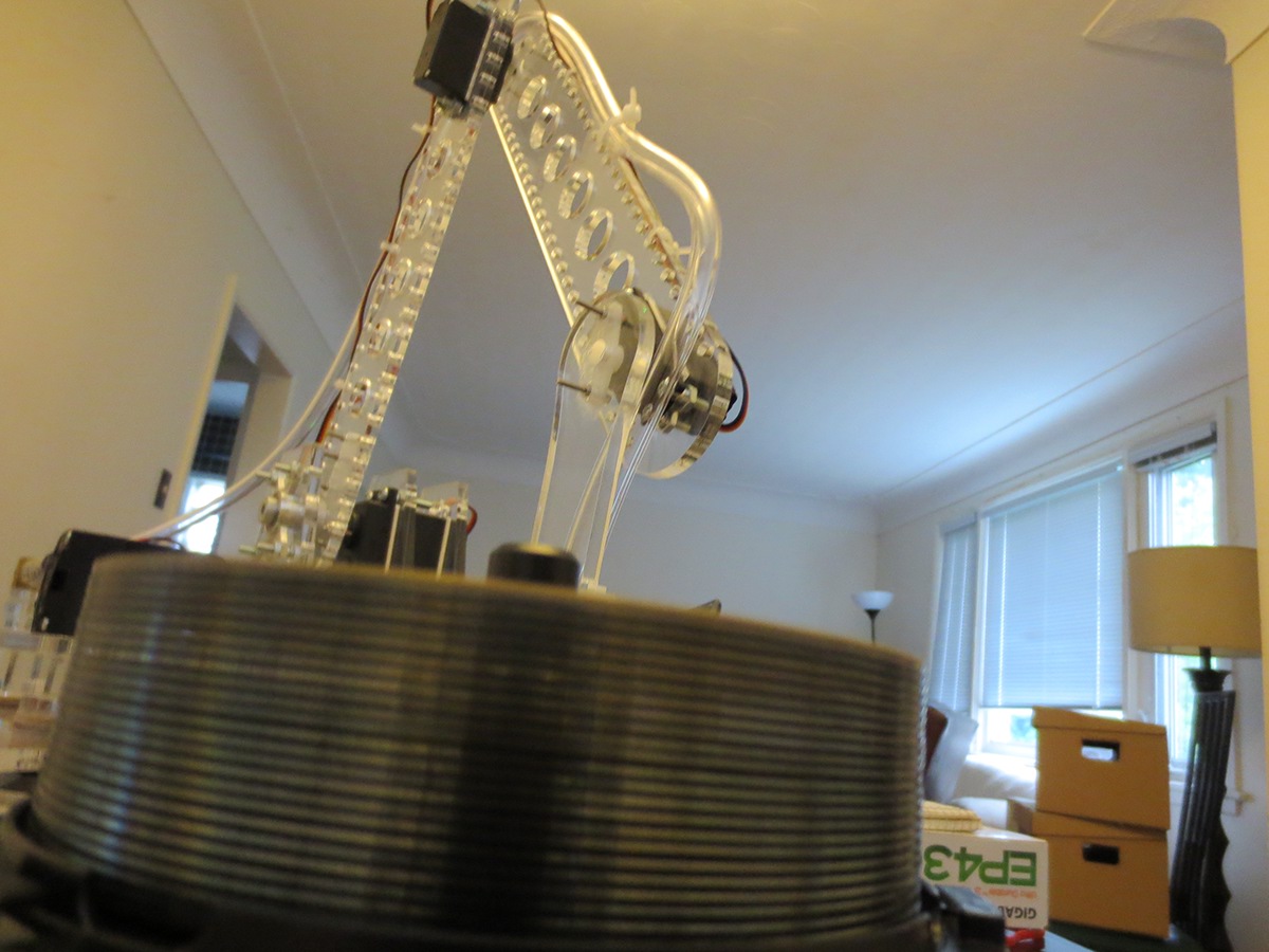
The CD stacks which will hold the burned and empty Compact Disks.

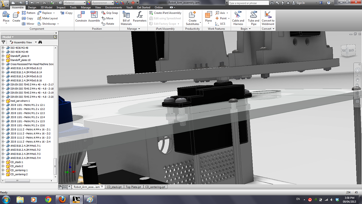
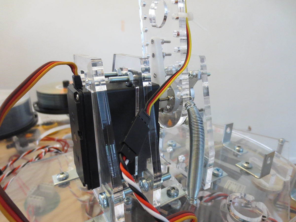
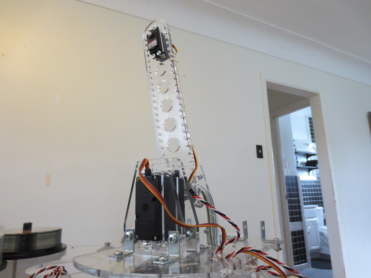
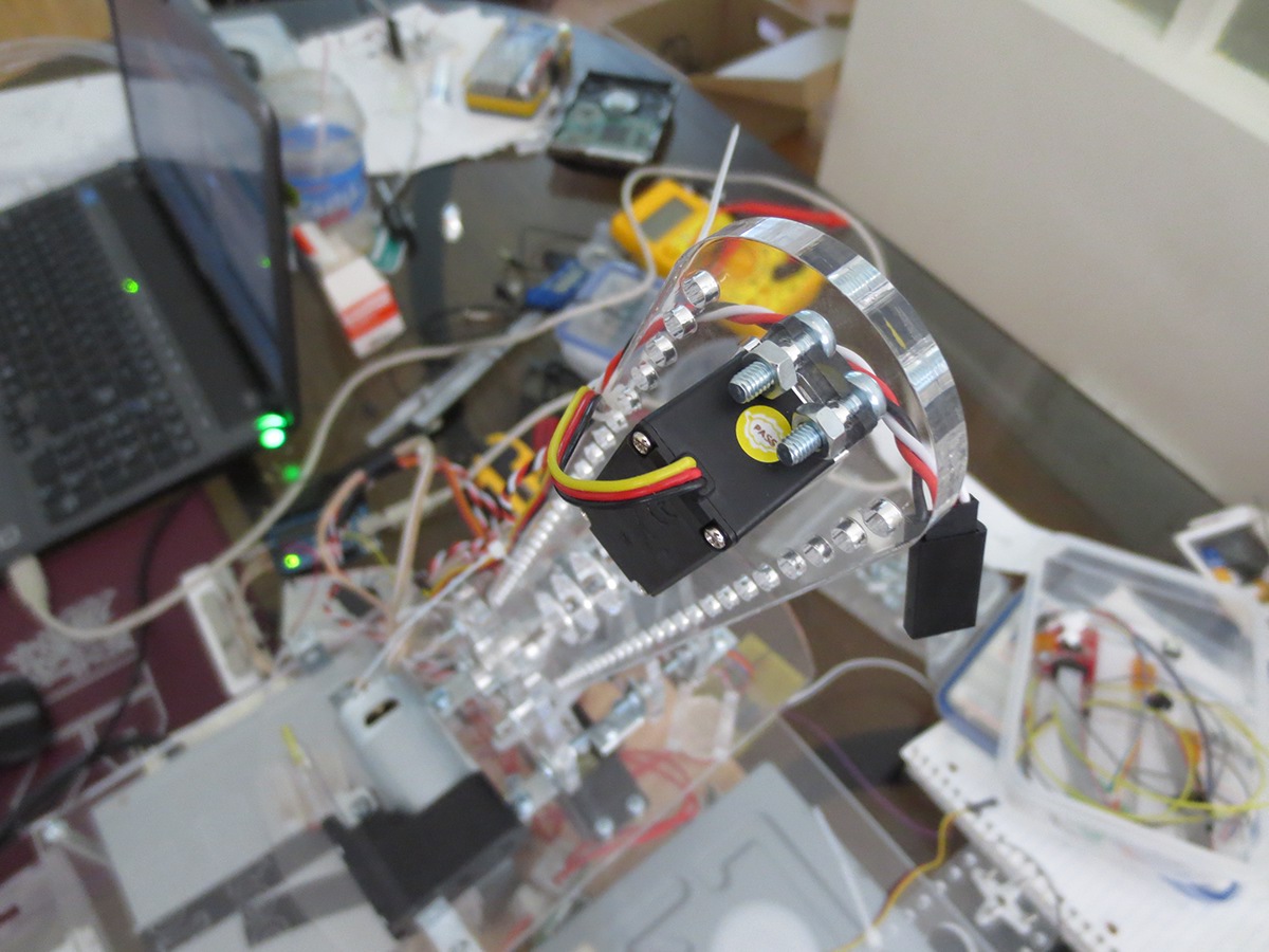
The servo mounted in the top plate to provide the arm with 140 degrees of rotation.
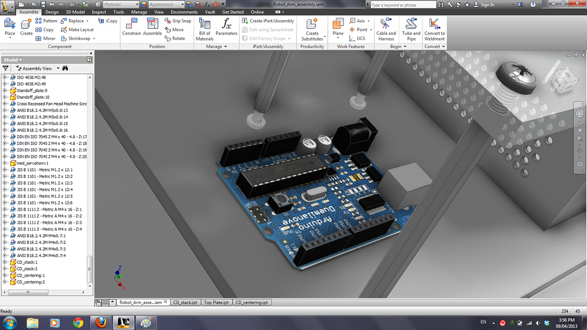
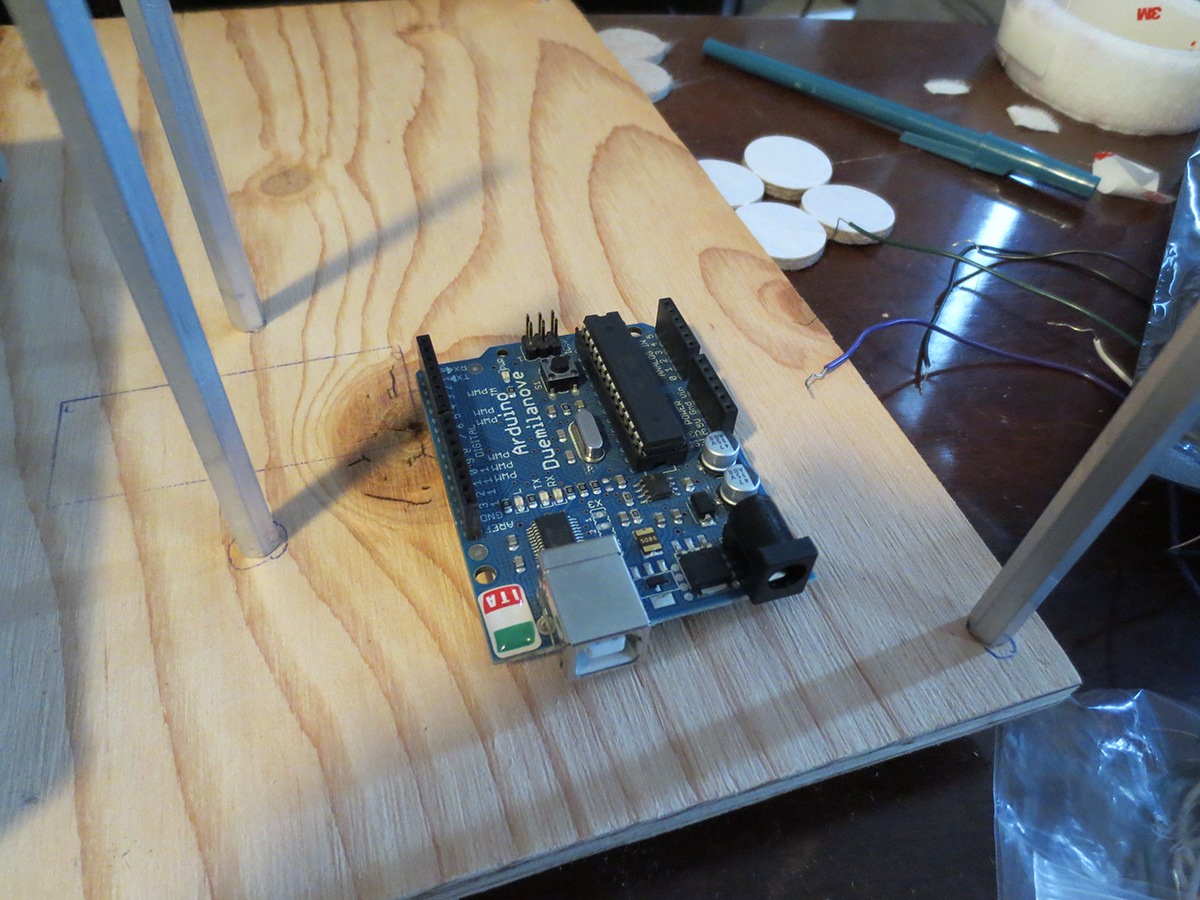
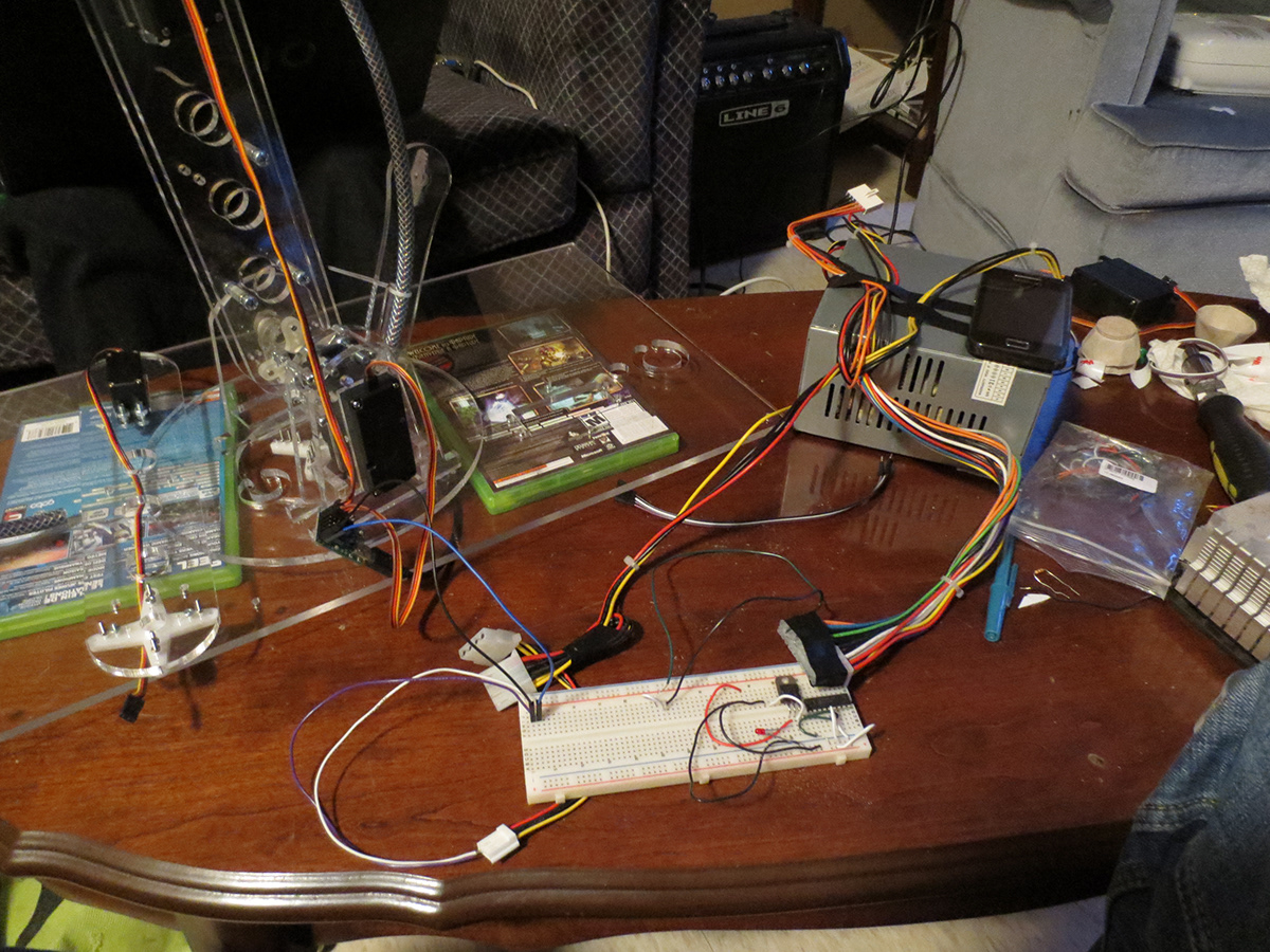
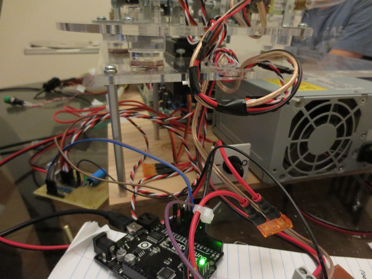
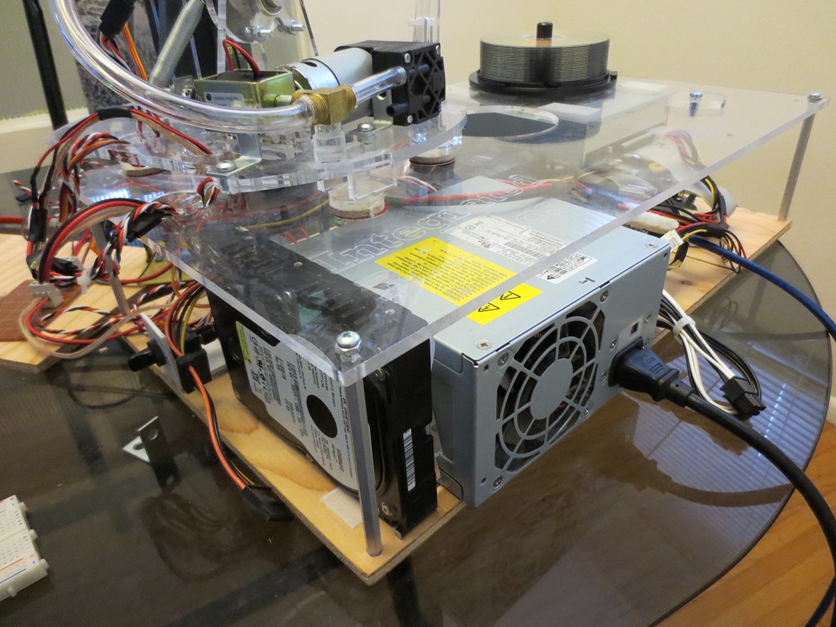
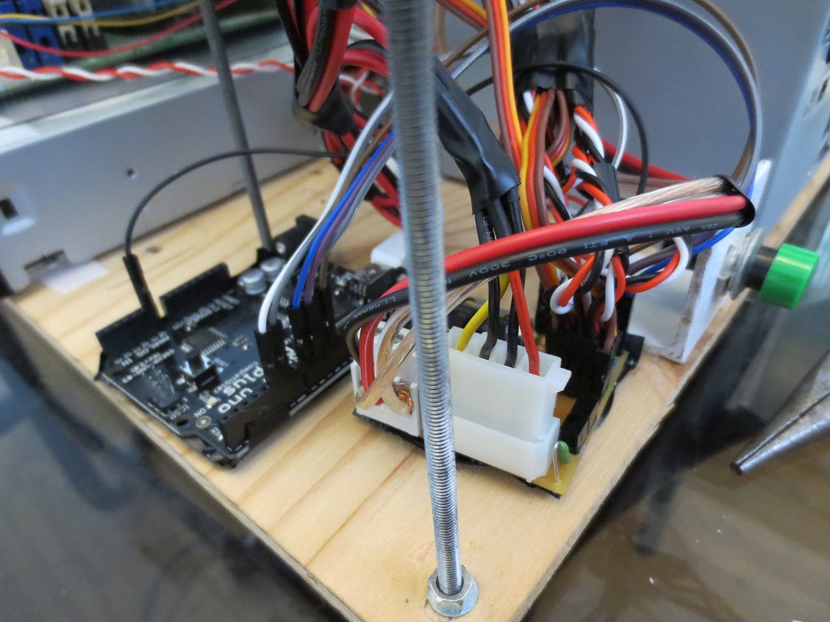
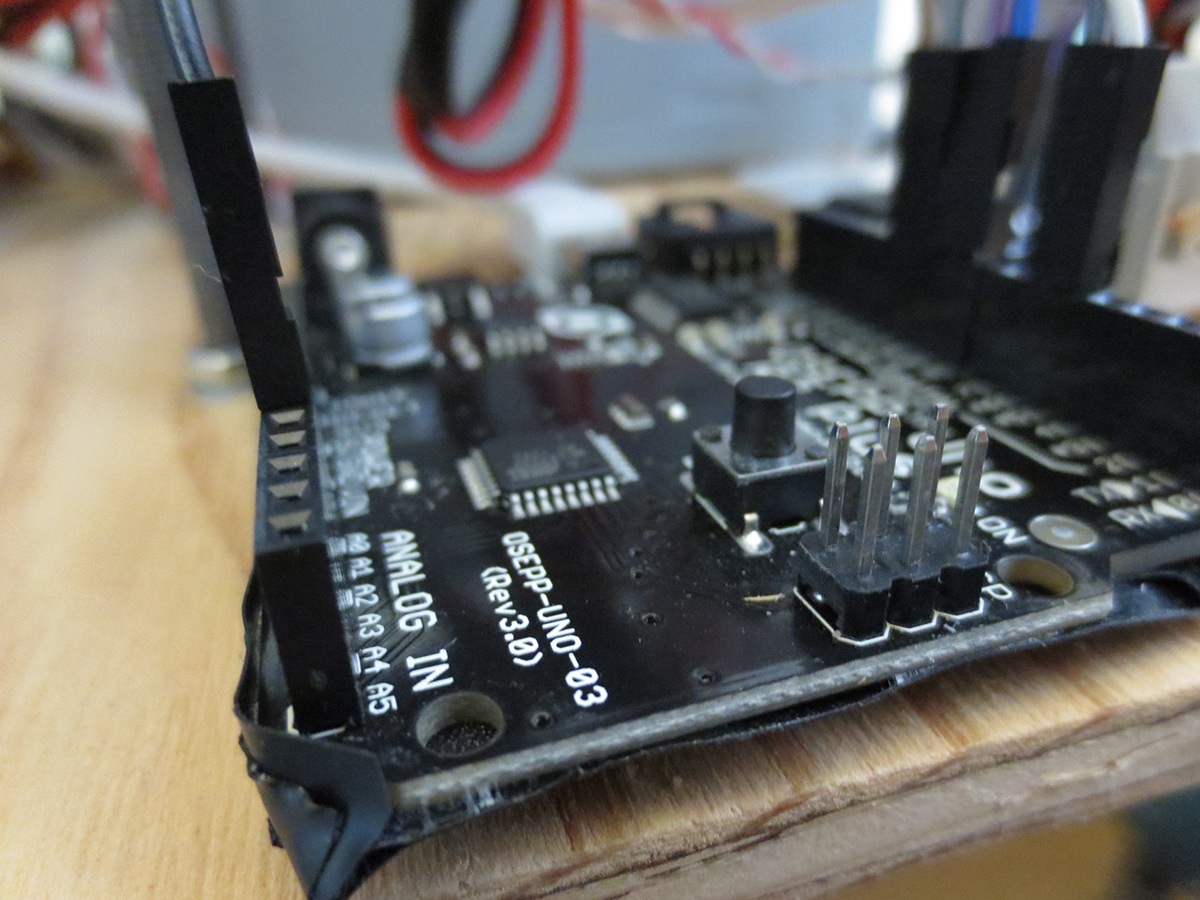
We decided to use an Arduino as the main board to control the movement and operation of the arm. For our testing phase, a USB 3.0 cable will be attached to the board from a laptop which generates the spatial coordinates that the arm must follow and perform the specific tasks. After extensive testing we plan to replace a laptop with a Rasberry Pi which will control both the motherboard and the Arduino, making the robot autonomous.
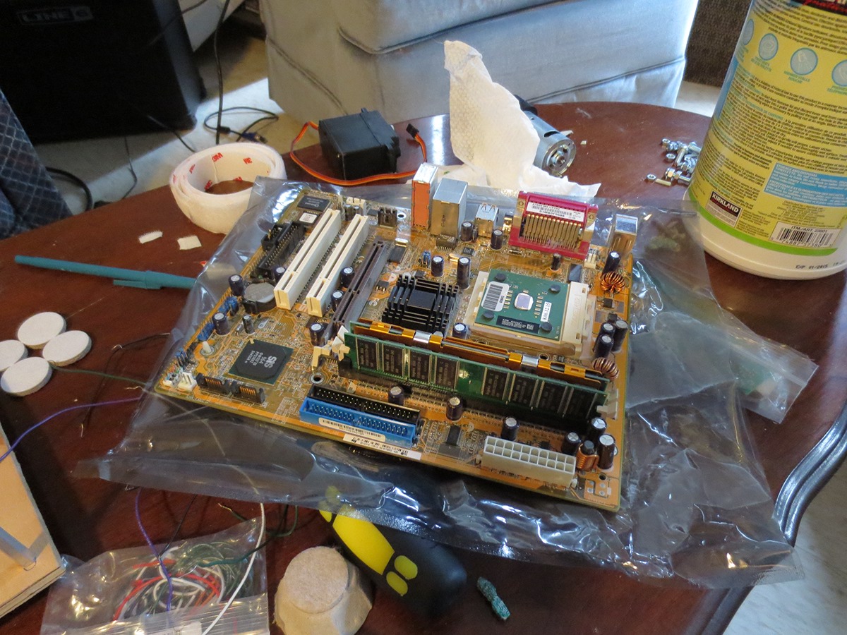
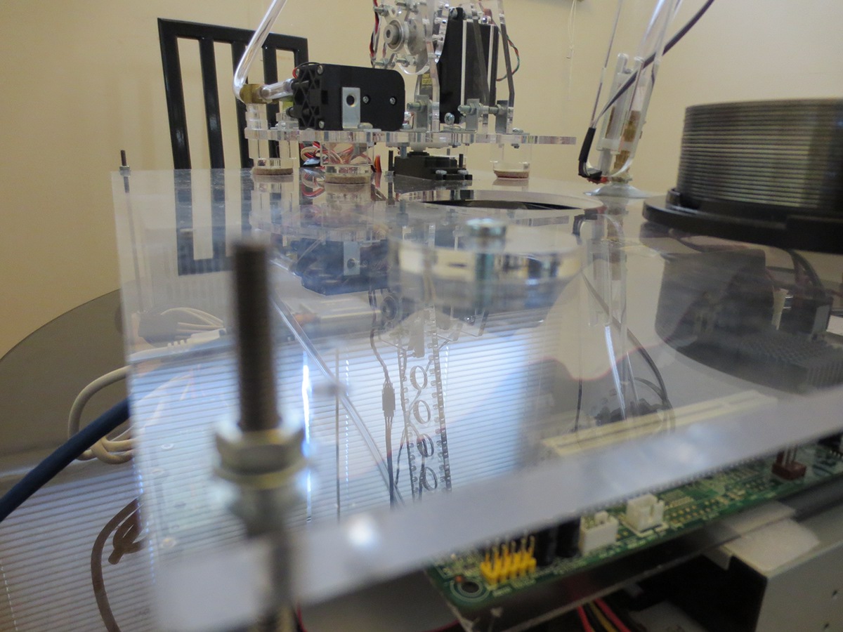
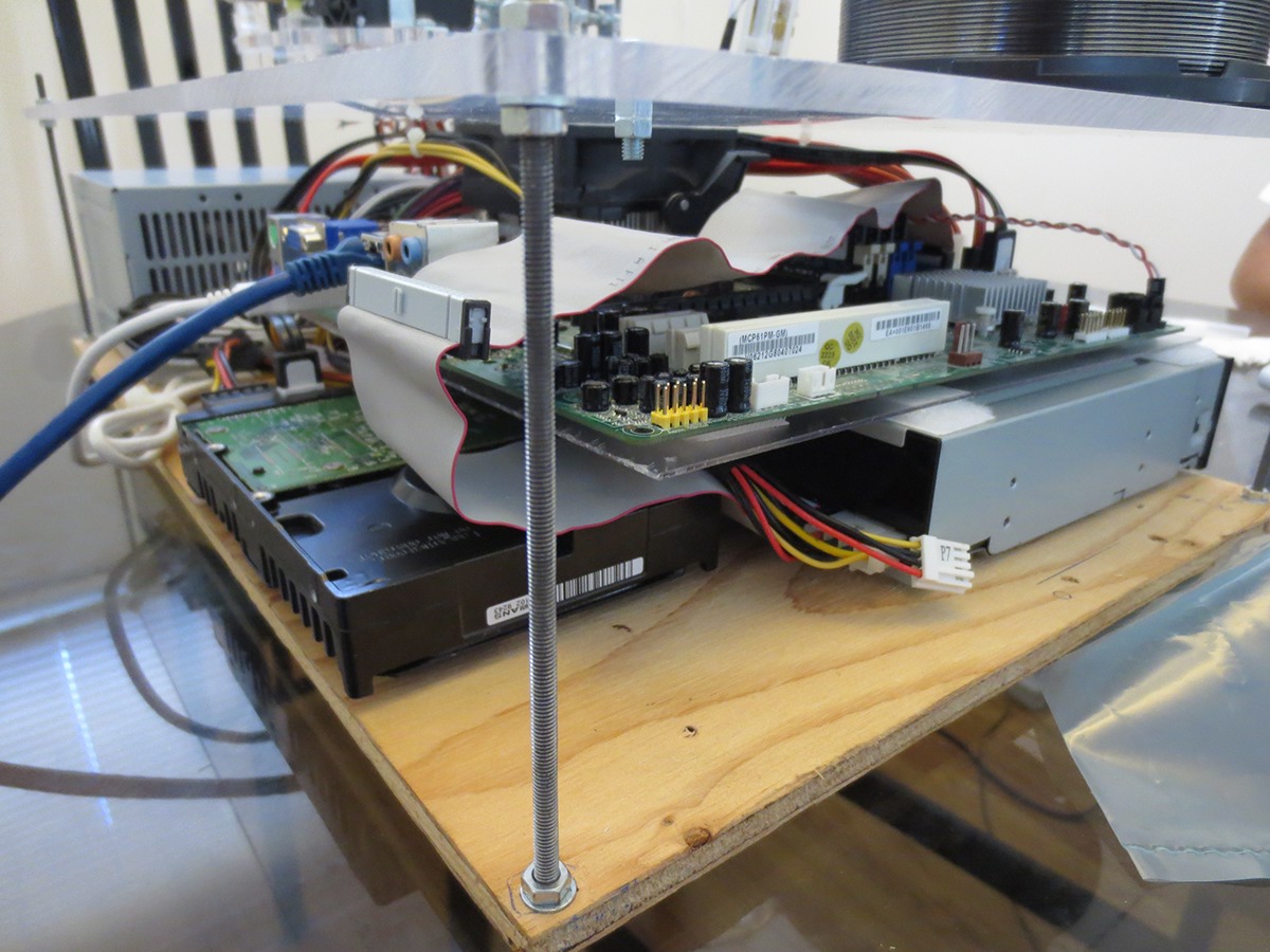
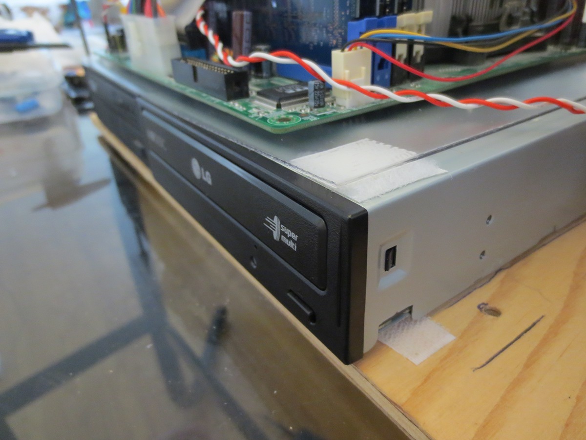
The motherboard's single purpose is to control the CD drives, access the RAM and burn CDs. This will also be operated by the RasberryPi once the testing phase is complete.
The motherboard's single purpose is to control the CD drives, access the RAM and burn CDs. This will also be operated by the RasberryPi once the testing phase is complete.
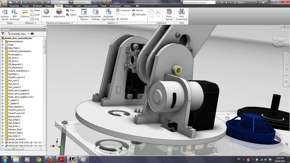
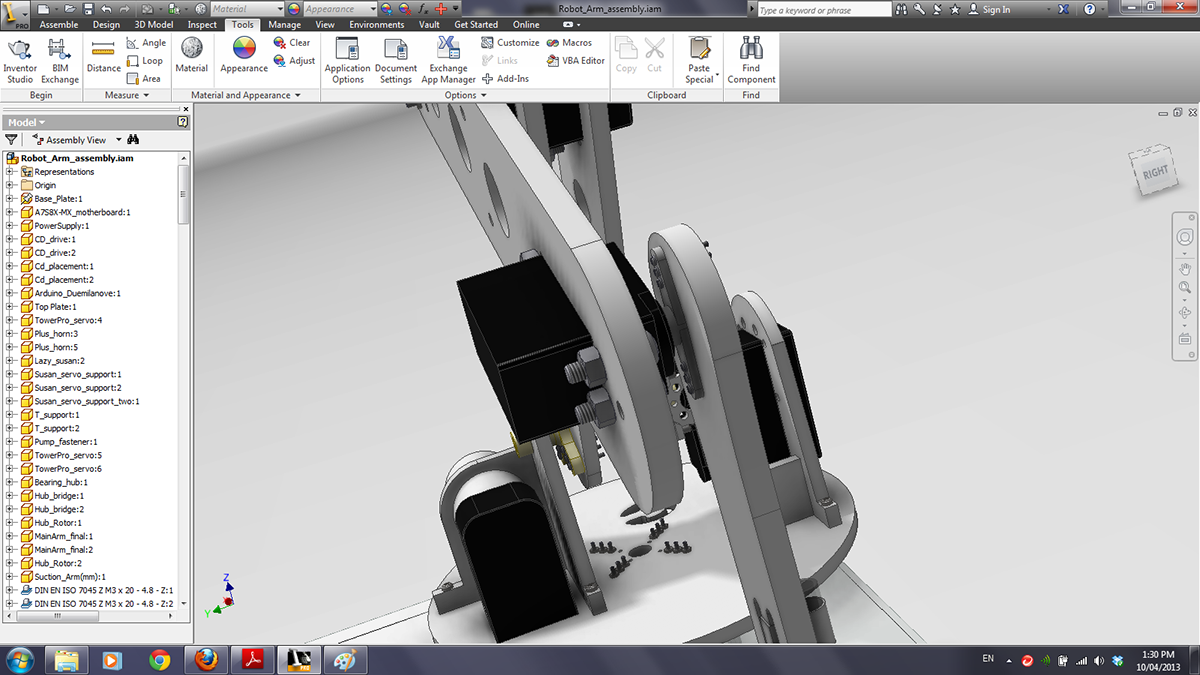
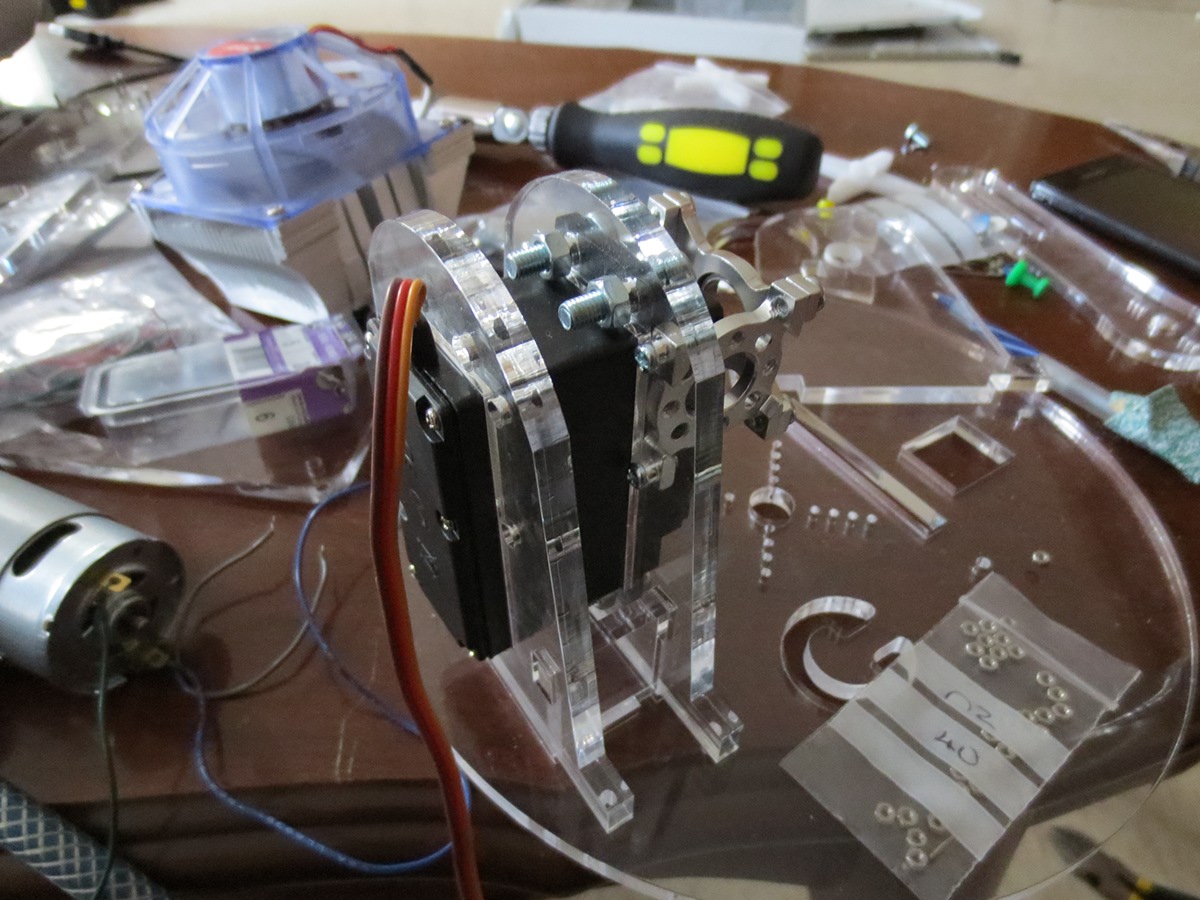
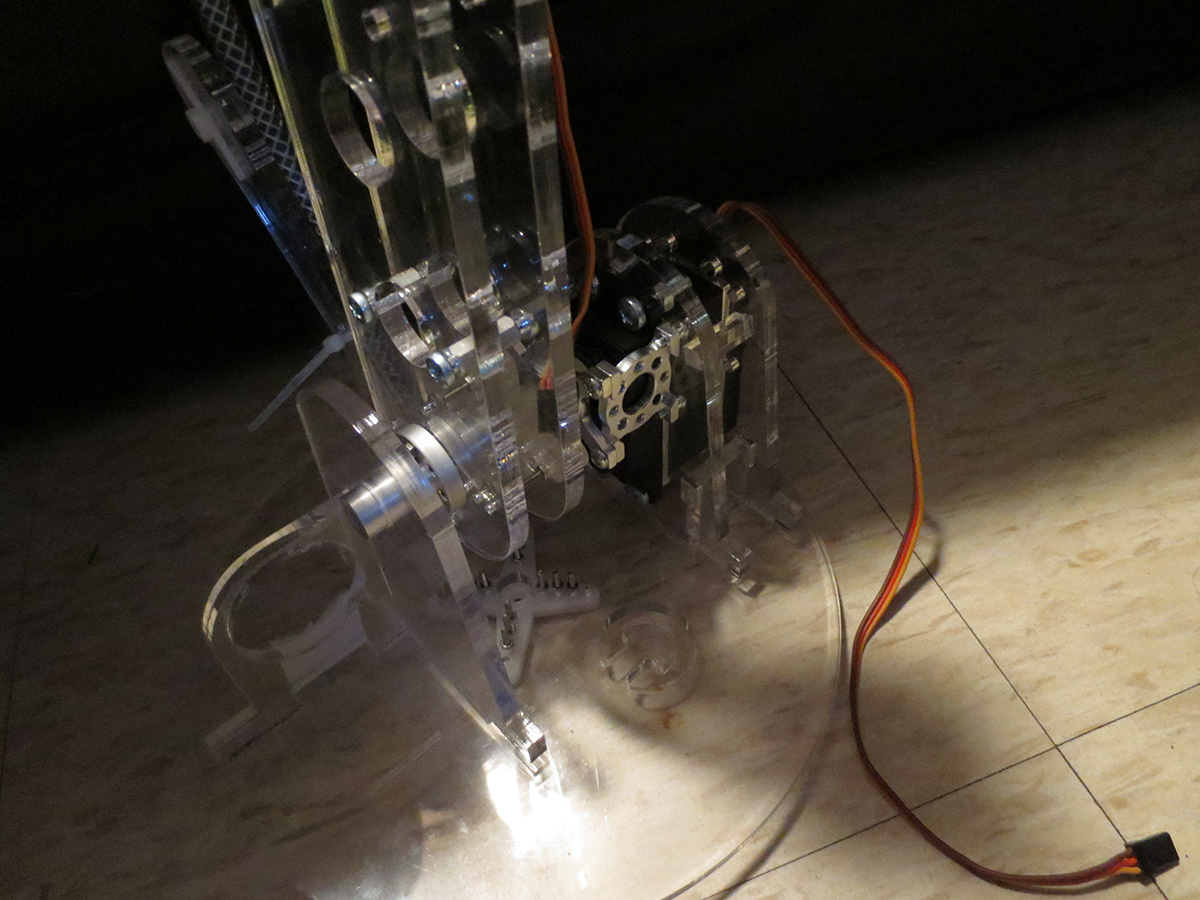
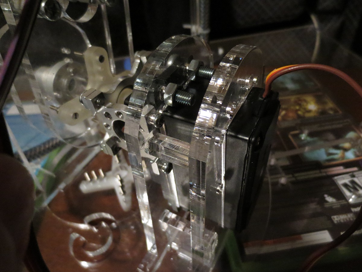
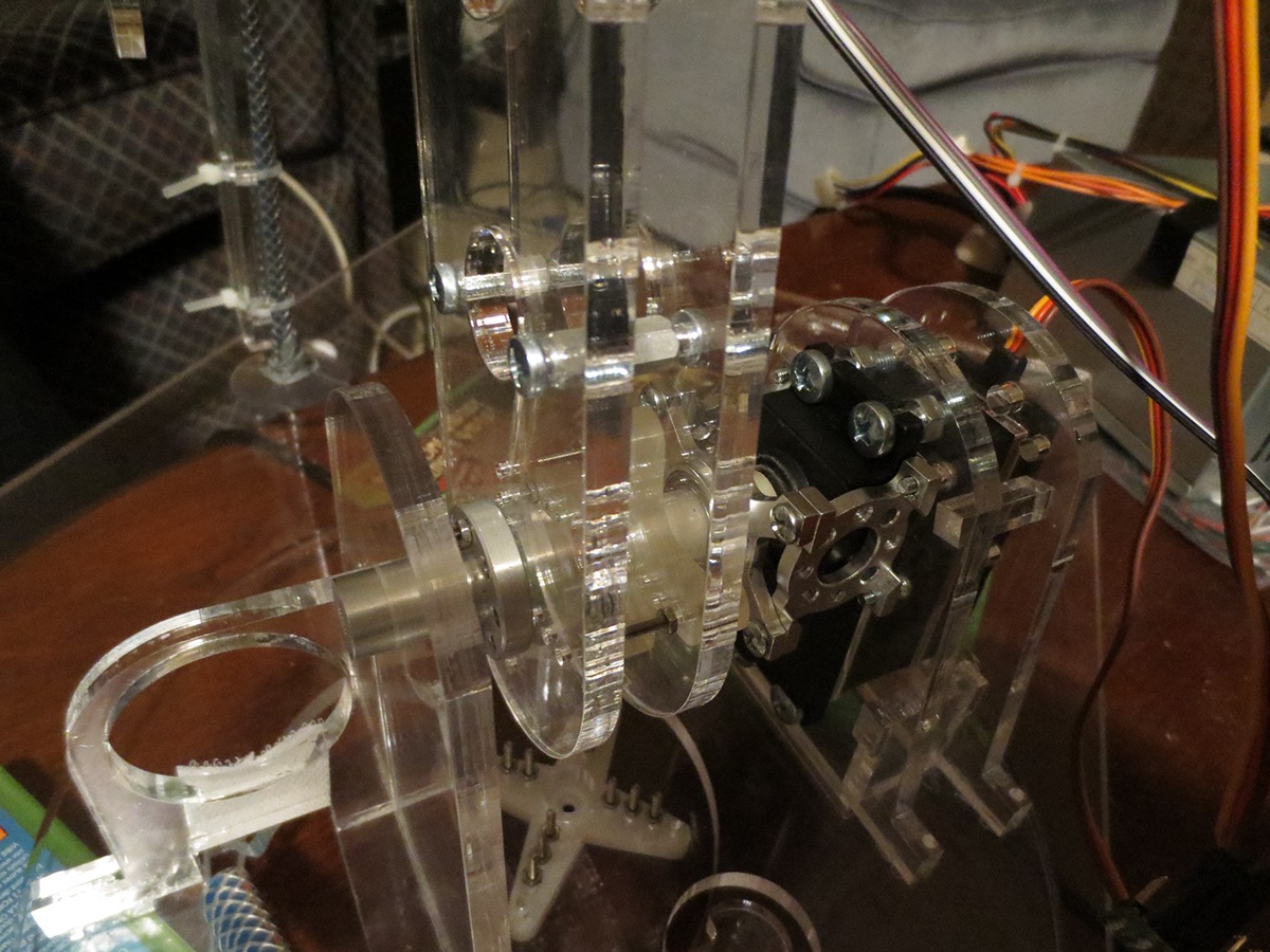
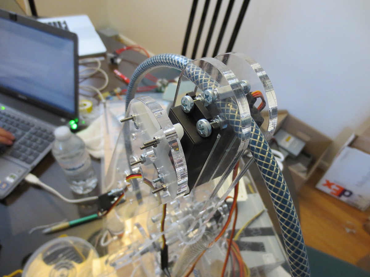
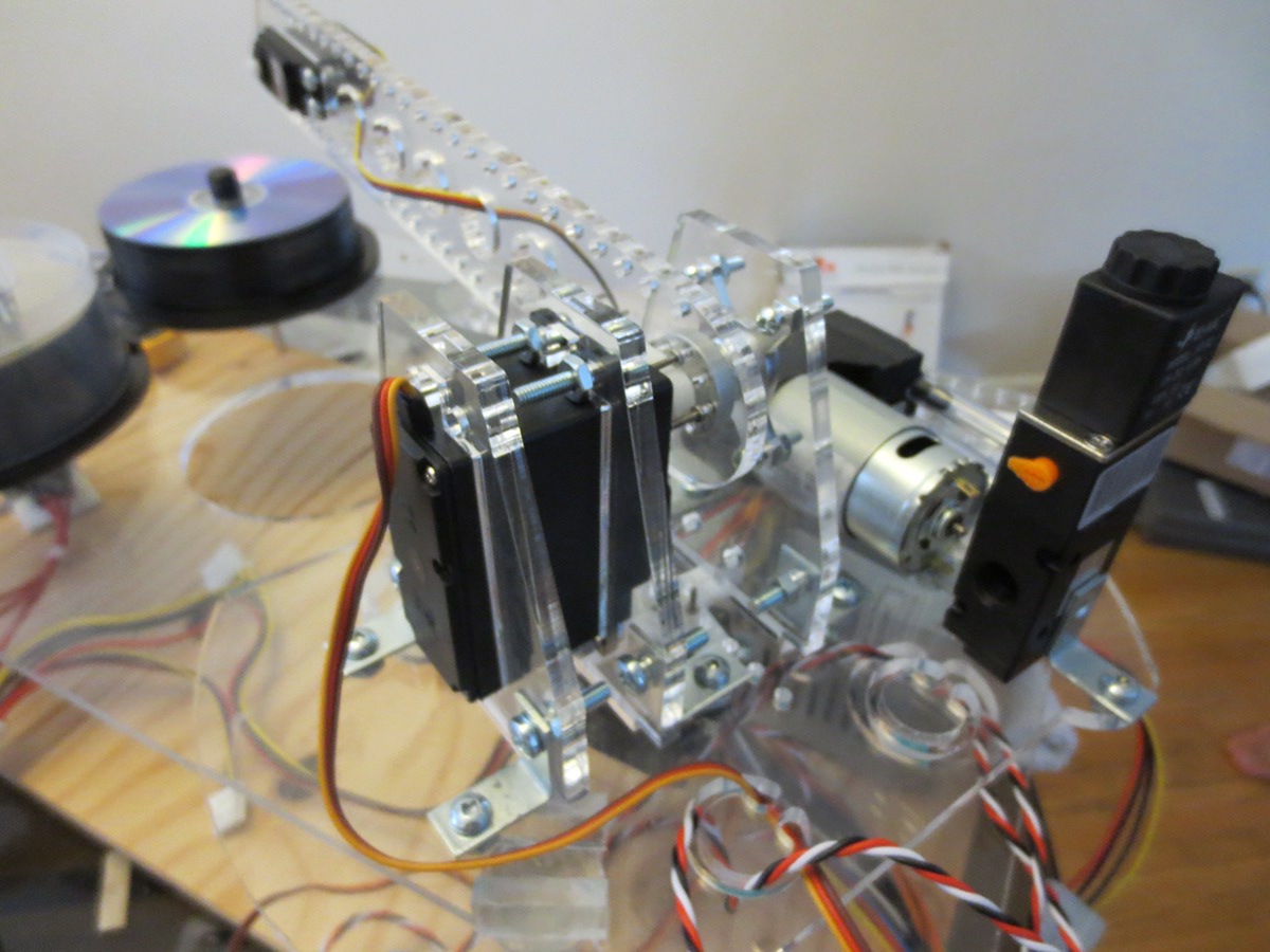
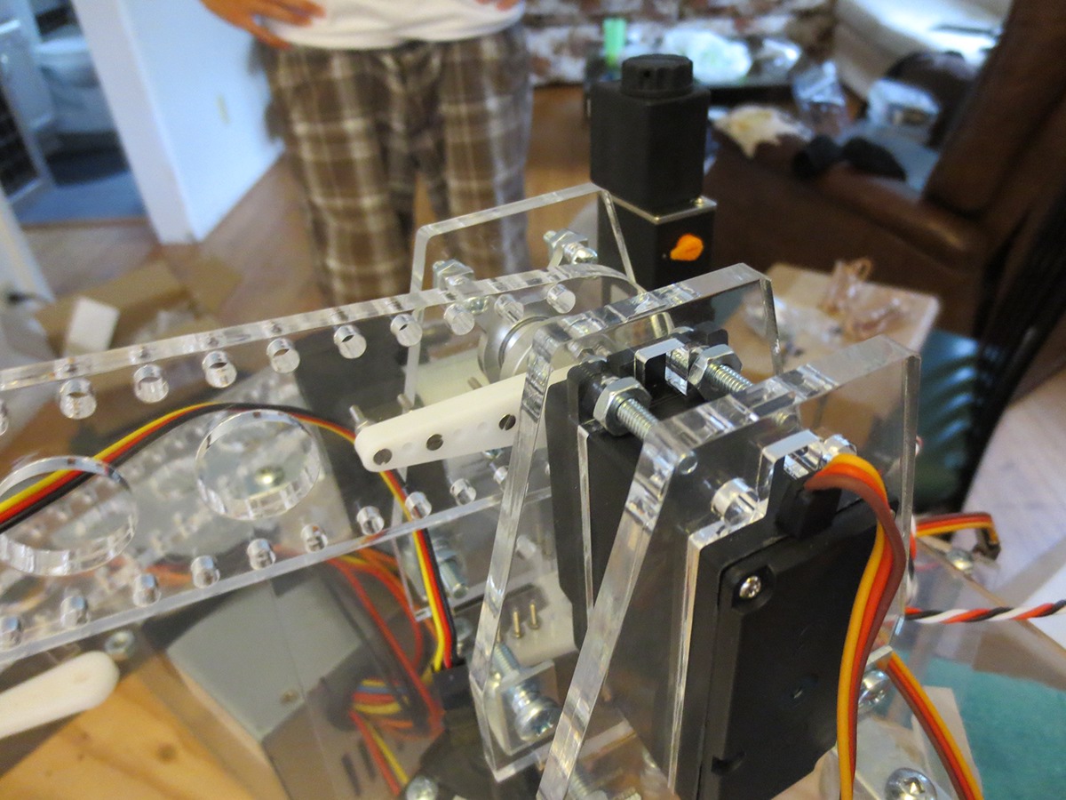
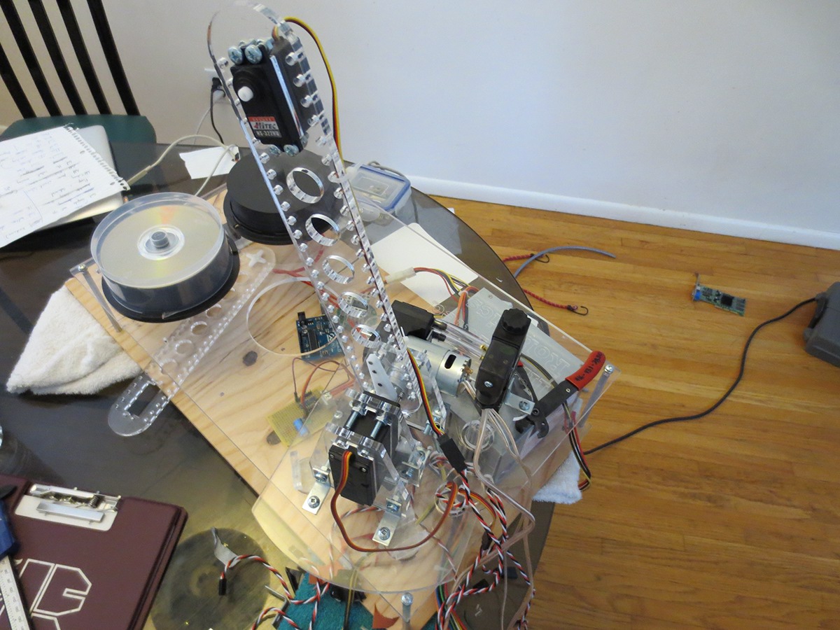
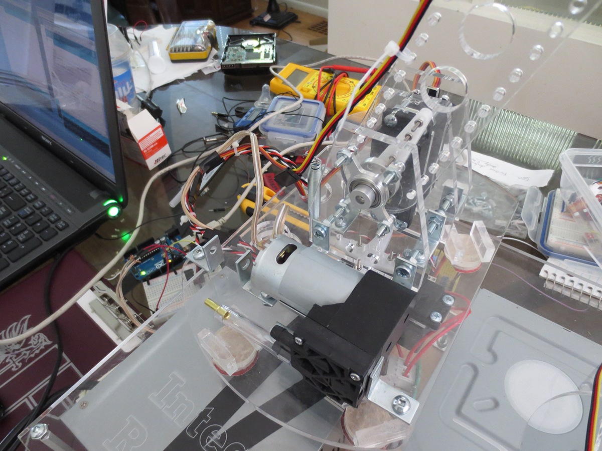
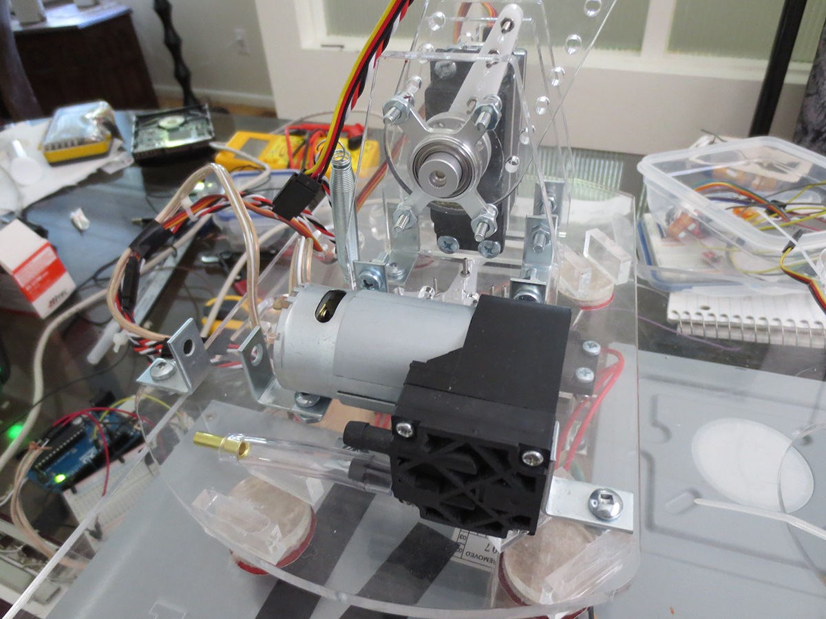
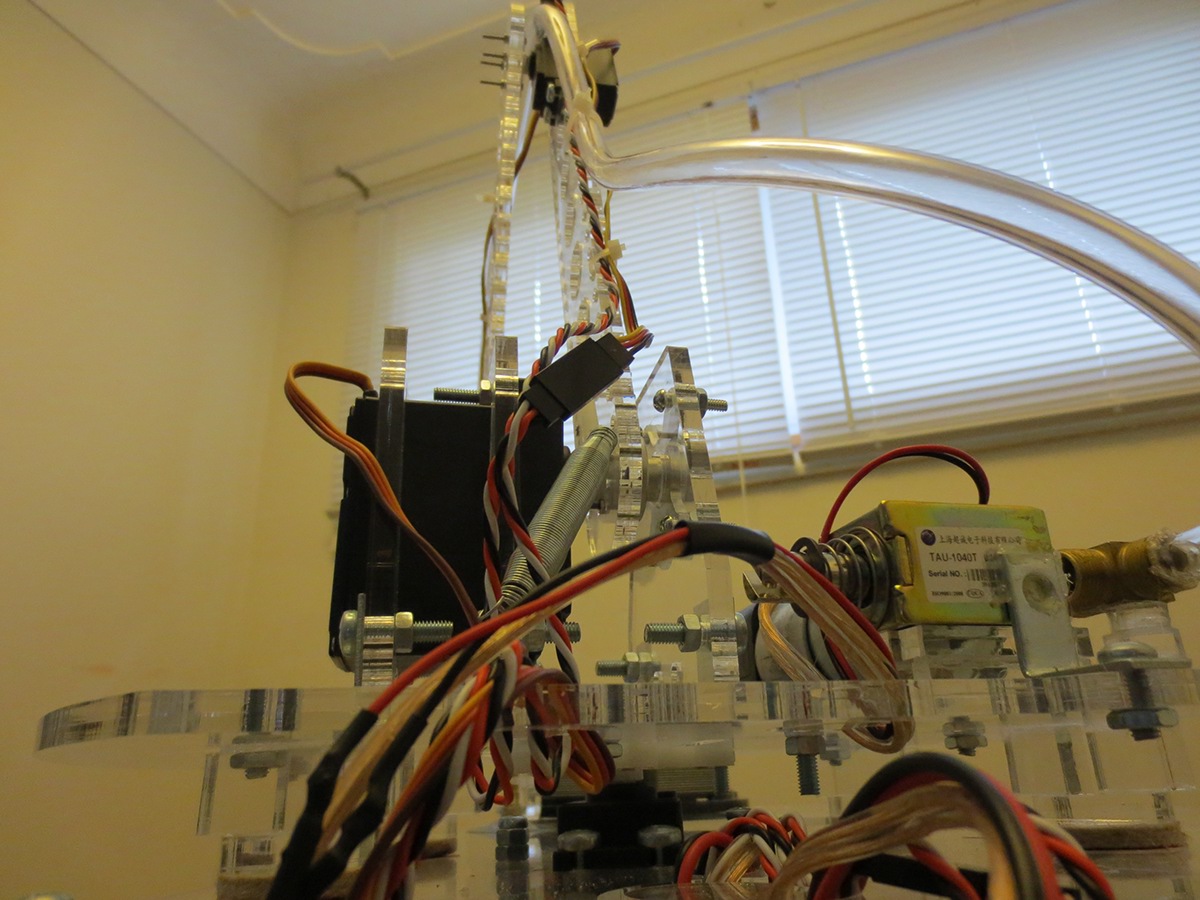
The rotary base of the arm. It includes a 20 Kg/cm servo, aluminum cast hub mounts, a vacuum pump and two 3D printed rotor hubs.
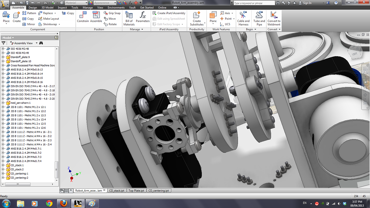

The joint between the large and medium arms.
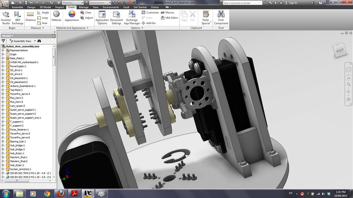
The joint between the medium and small arms.

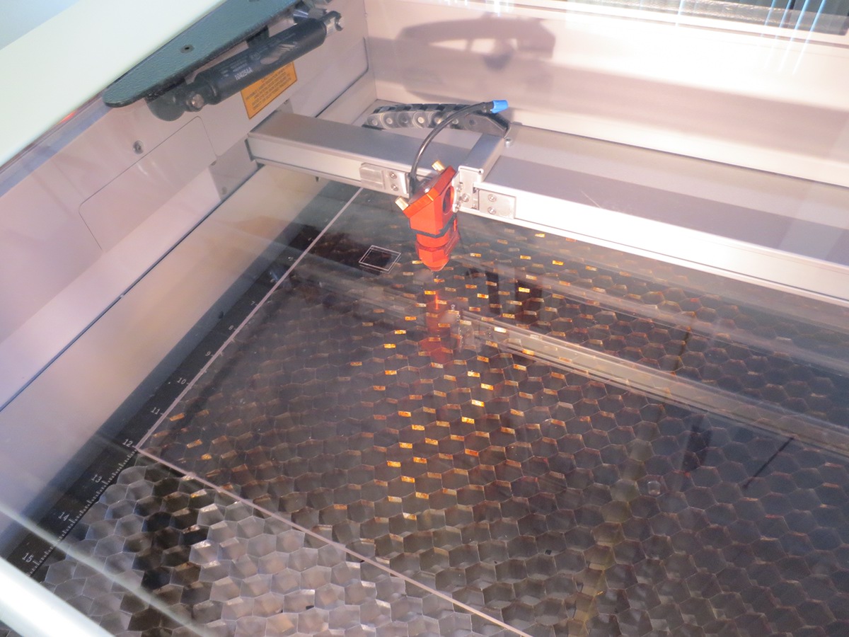
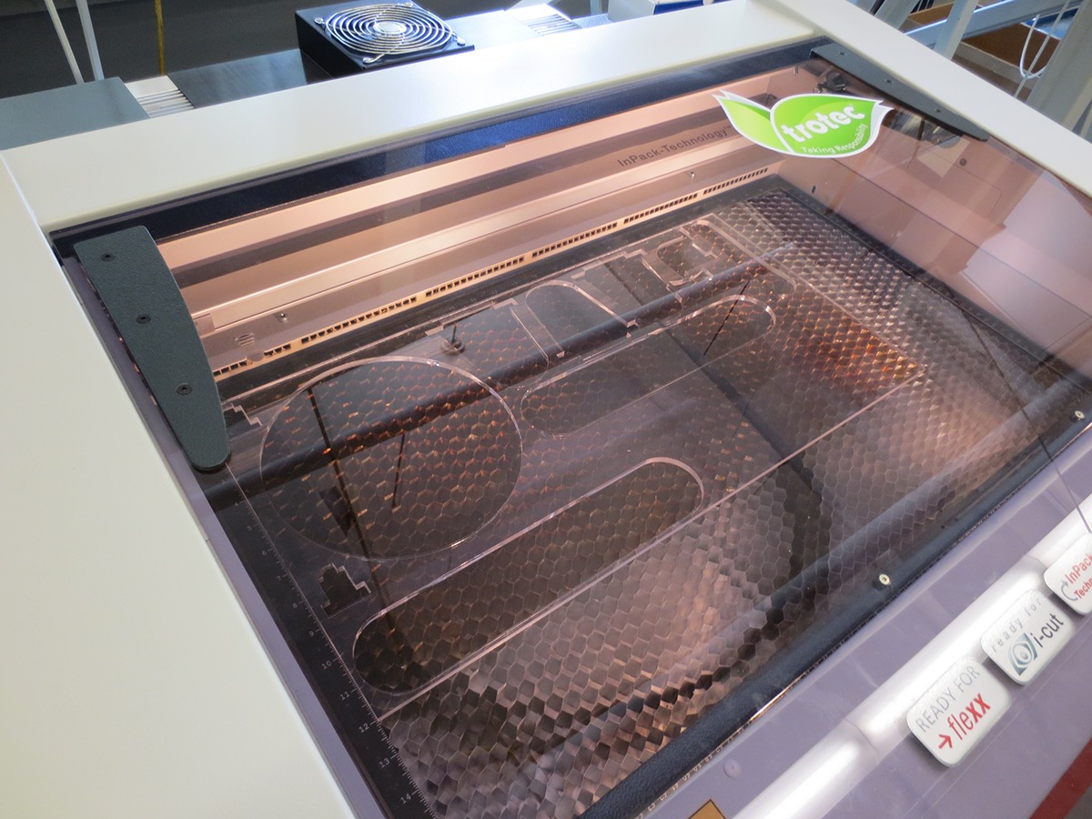
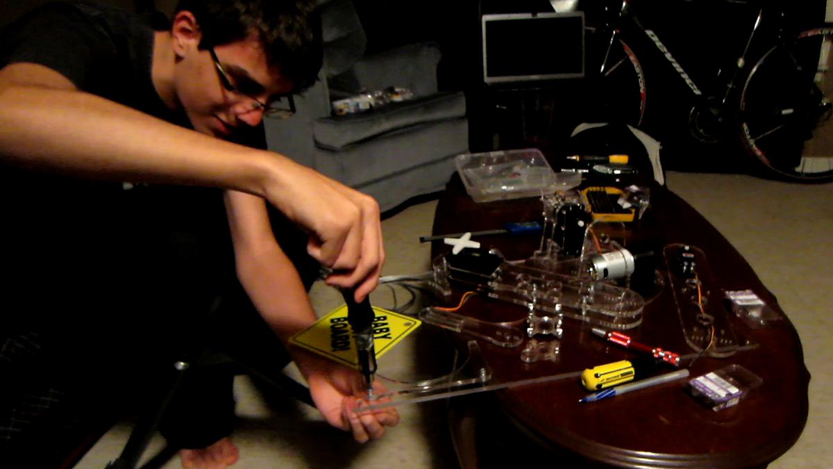
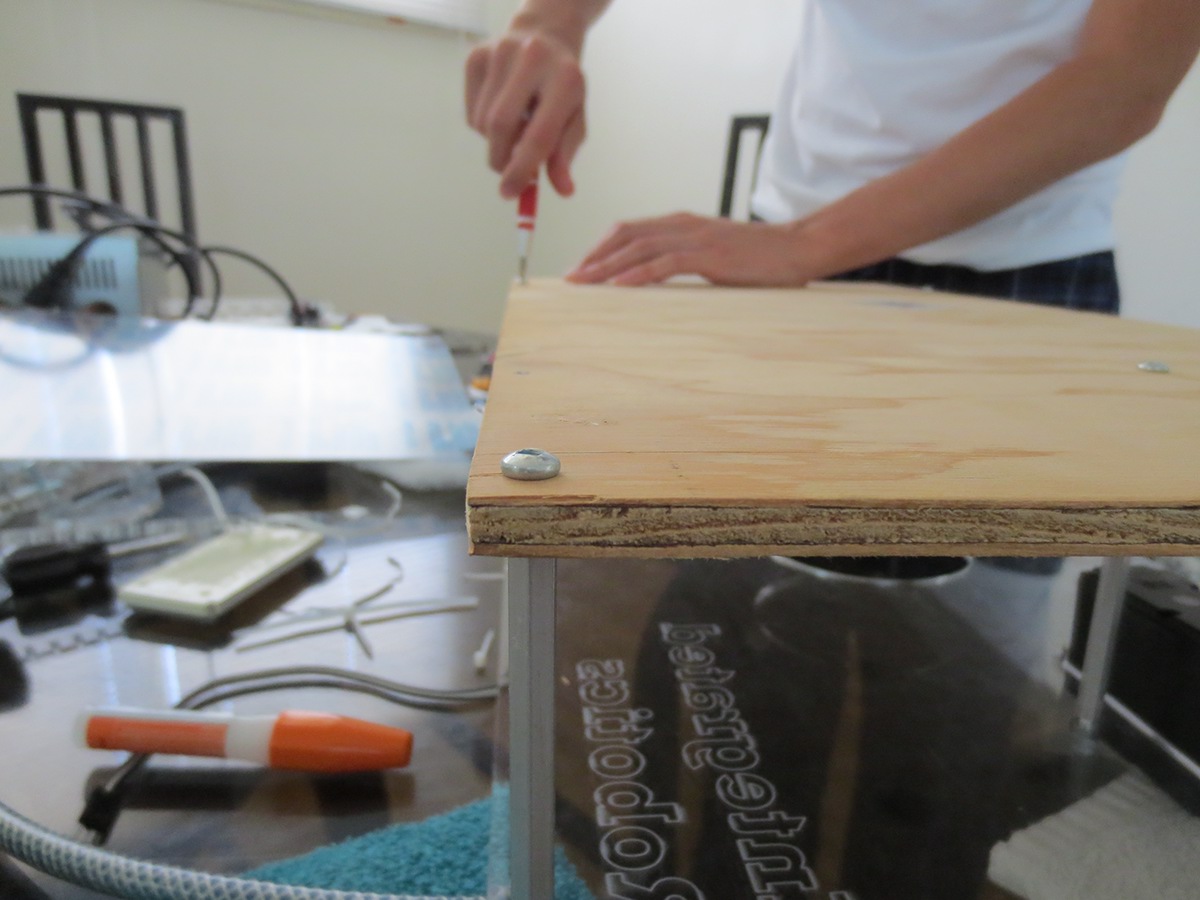
Using the laser cutter to cut out the robotic parts into acrylic glass sheets.
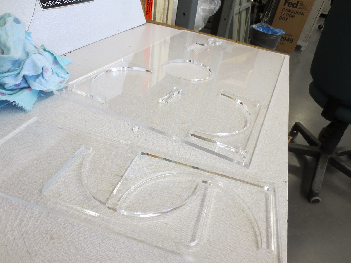
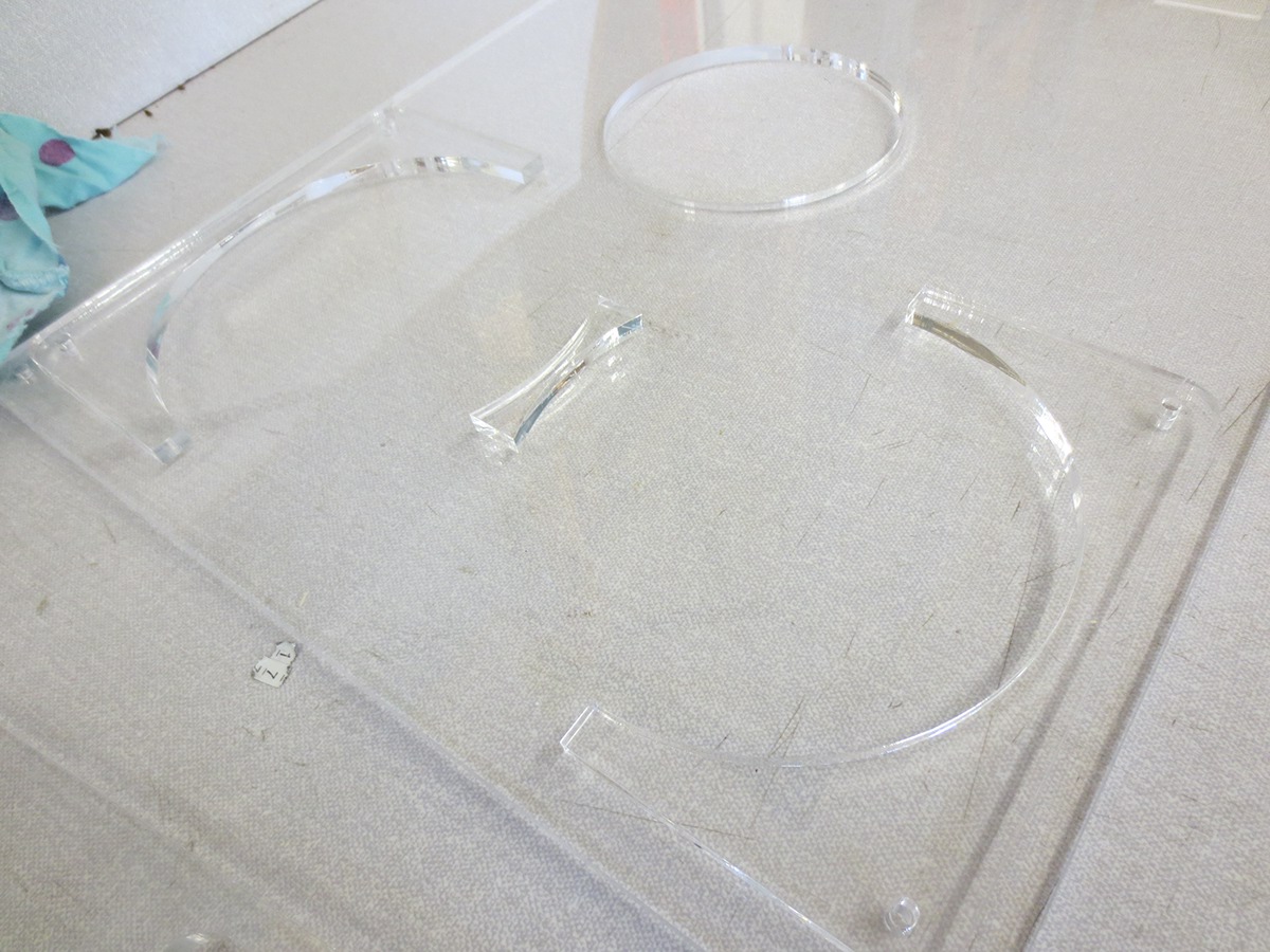
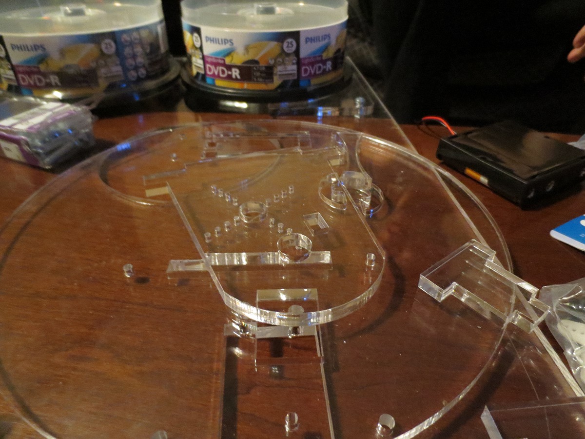
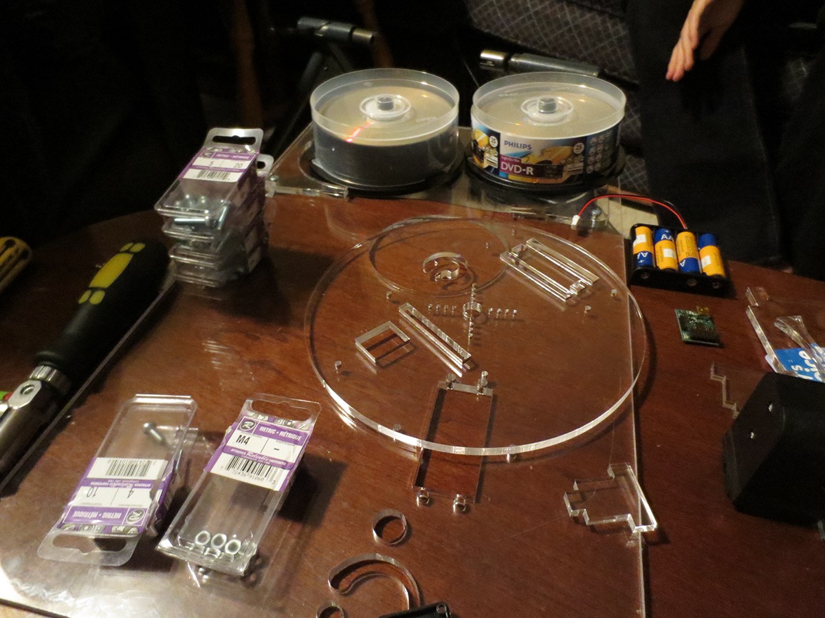
The cut outs of all the Inventor designed parts.
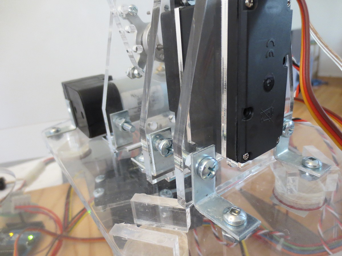
Mounting the servo to the base.

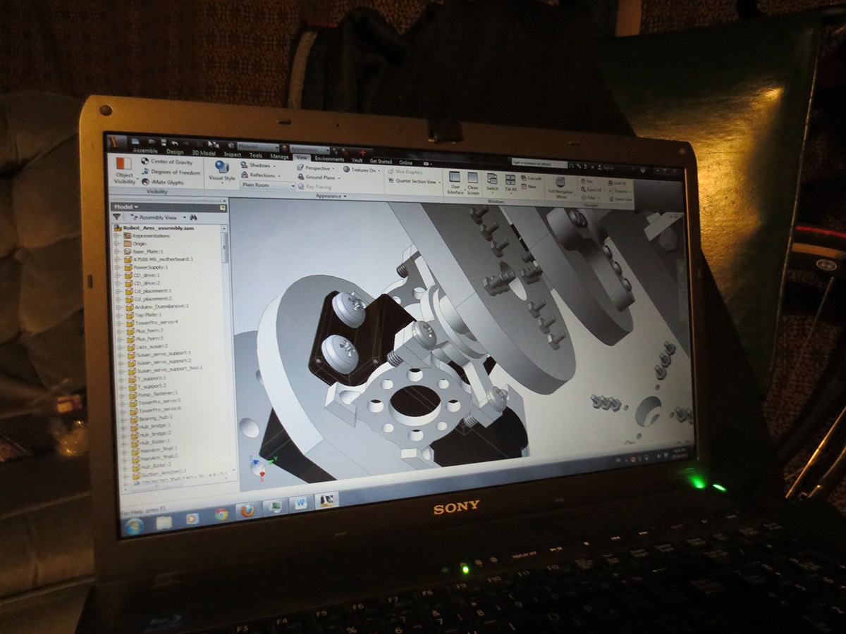
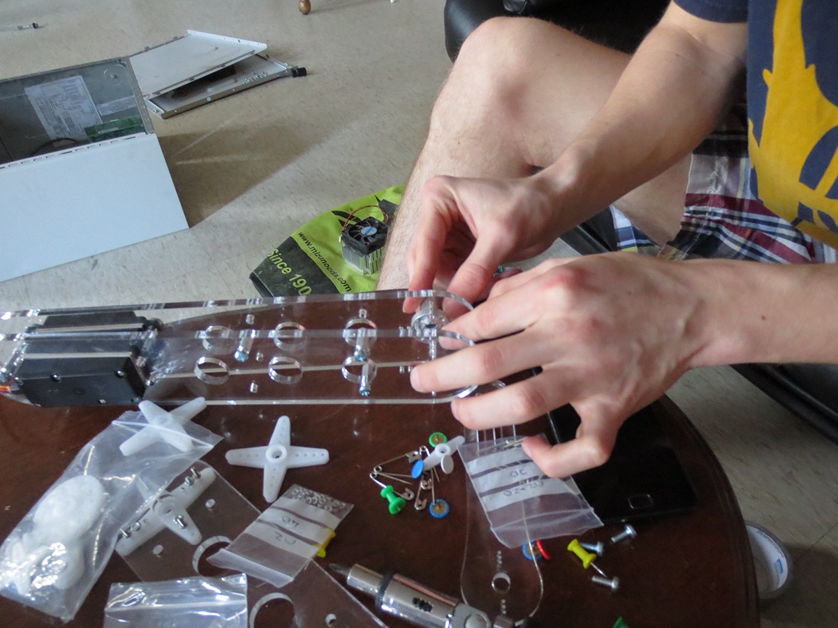
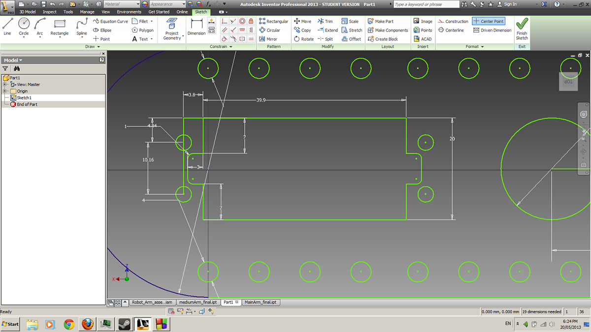
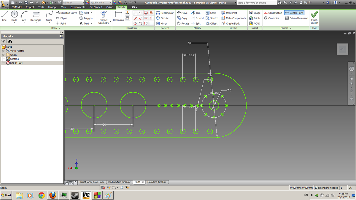
Checking the CAD design before applying all the fasteners to their position.

The vacuum pump that will provide the suction to pick up and drop Compact Disks.
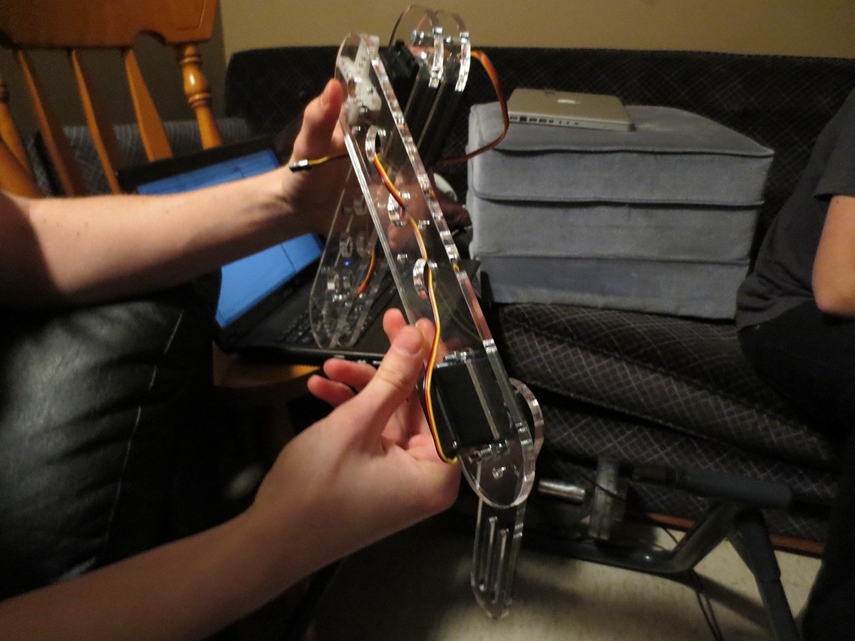
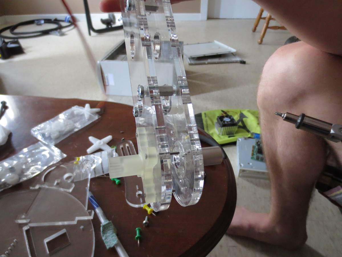
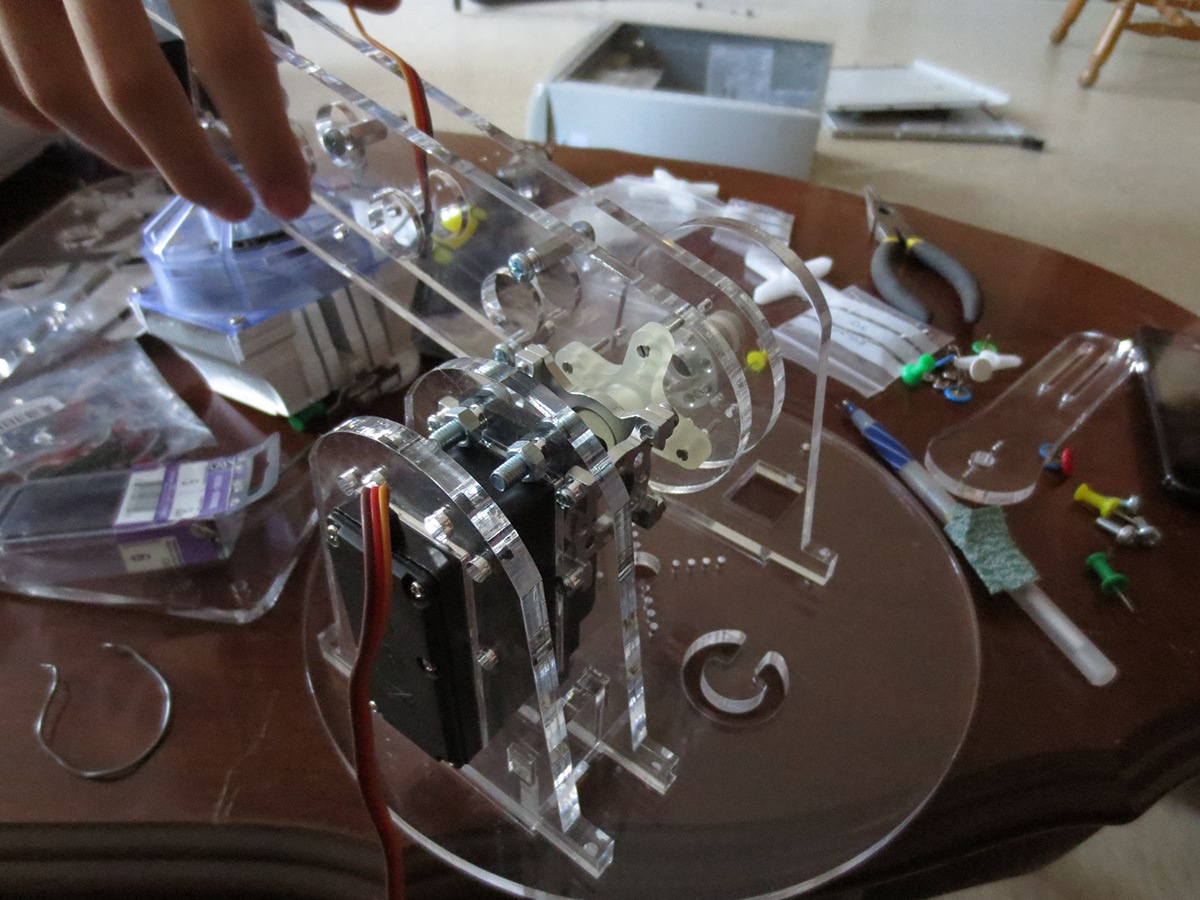
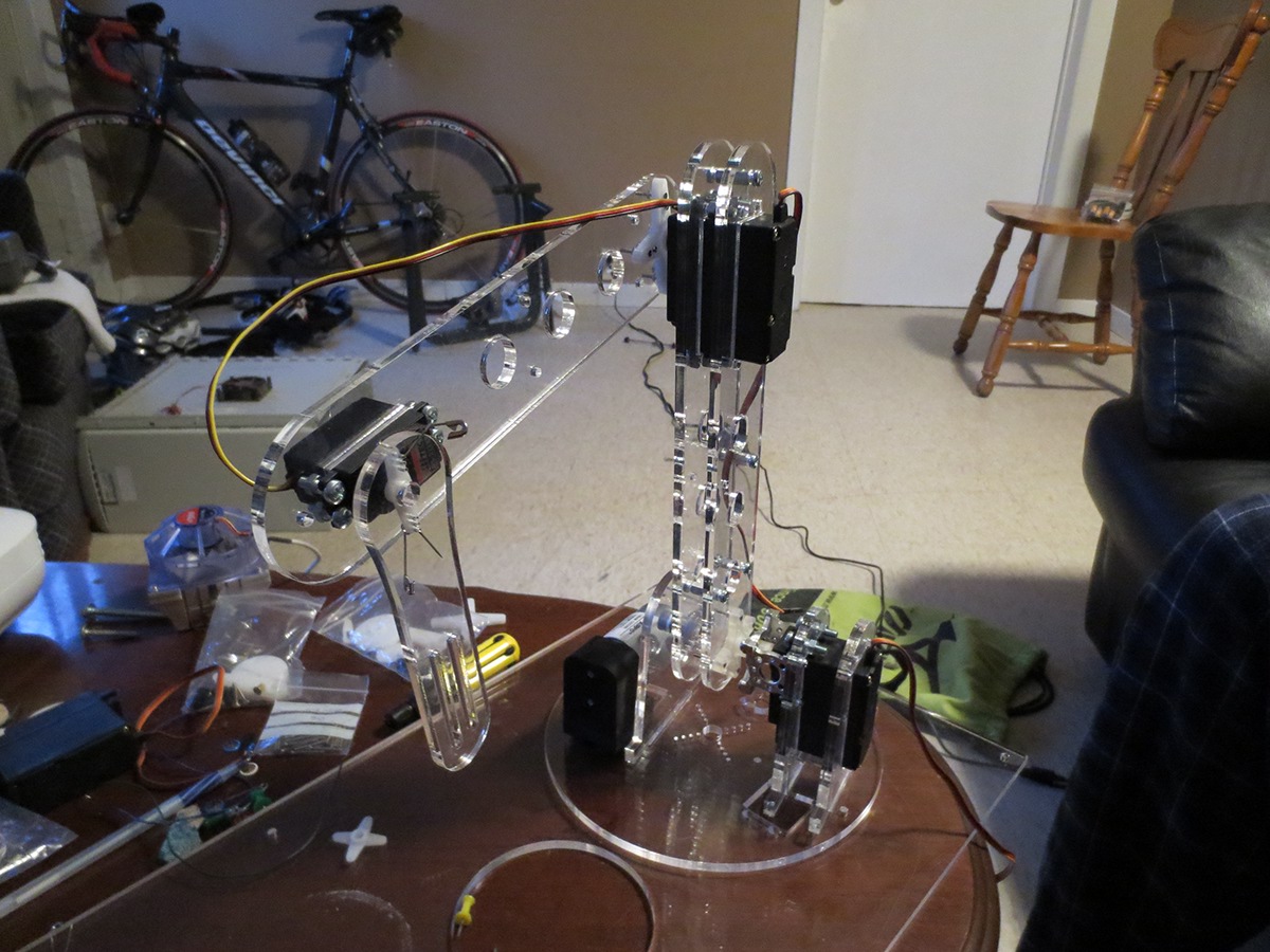
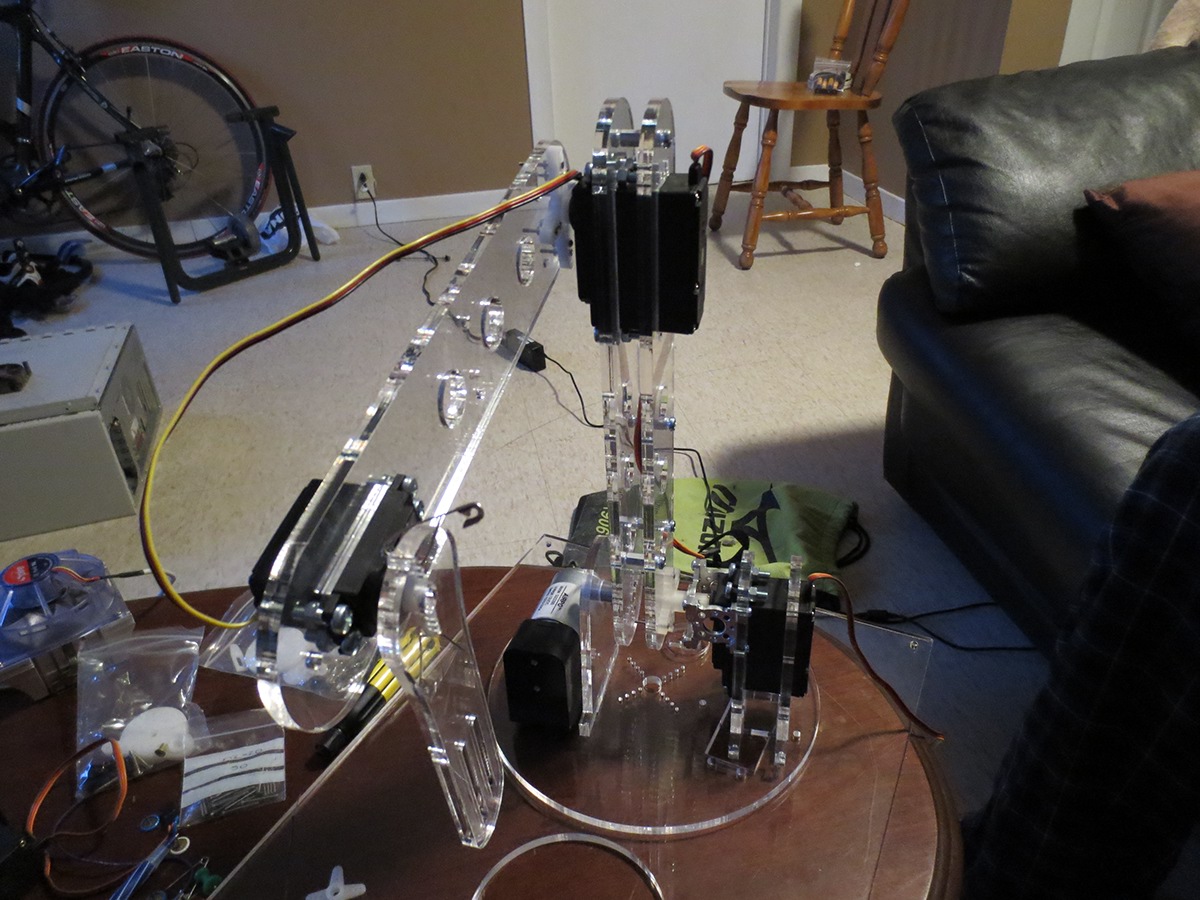
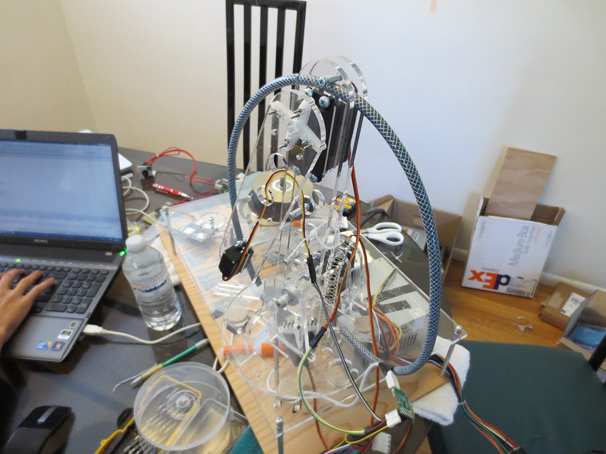
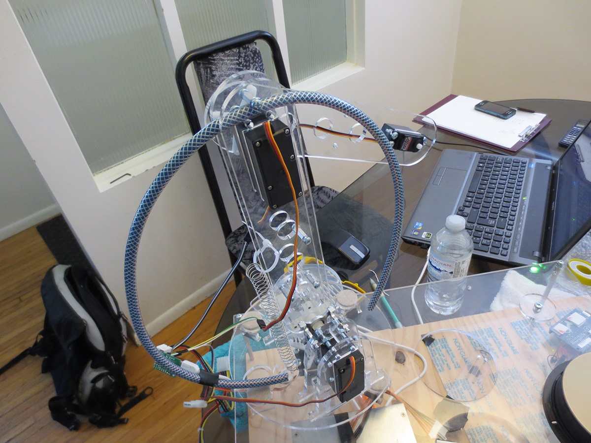
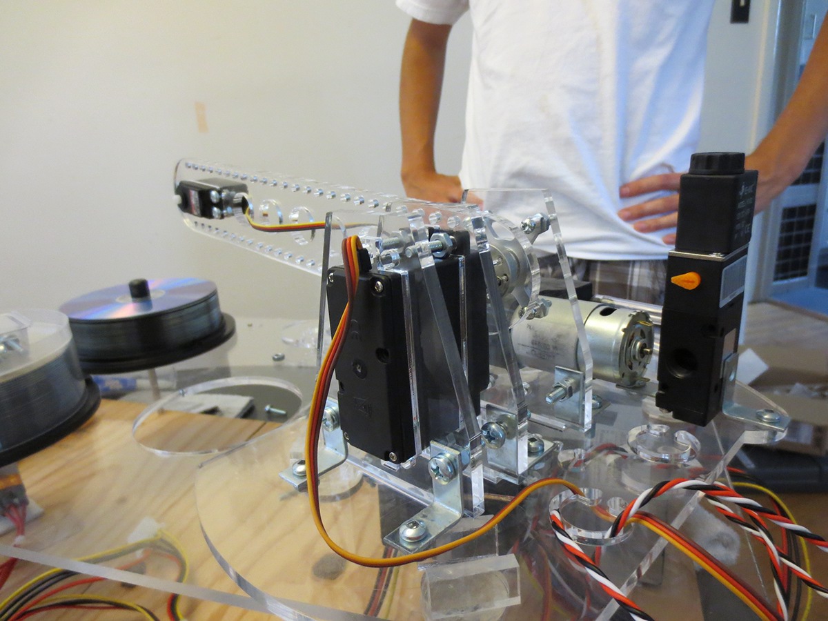
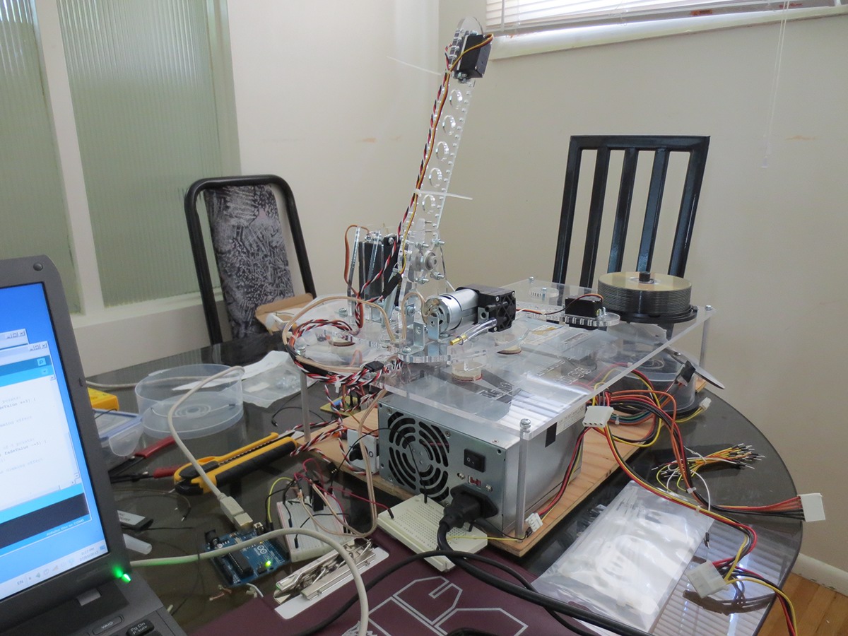
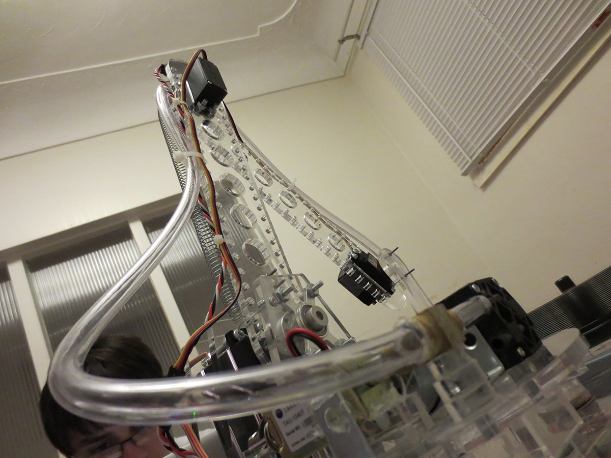
The robotic arm.

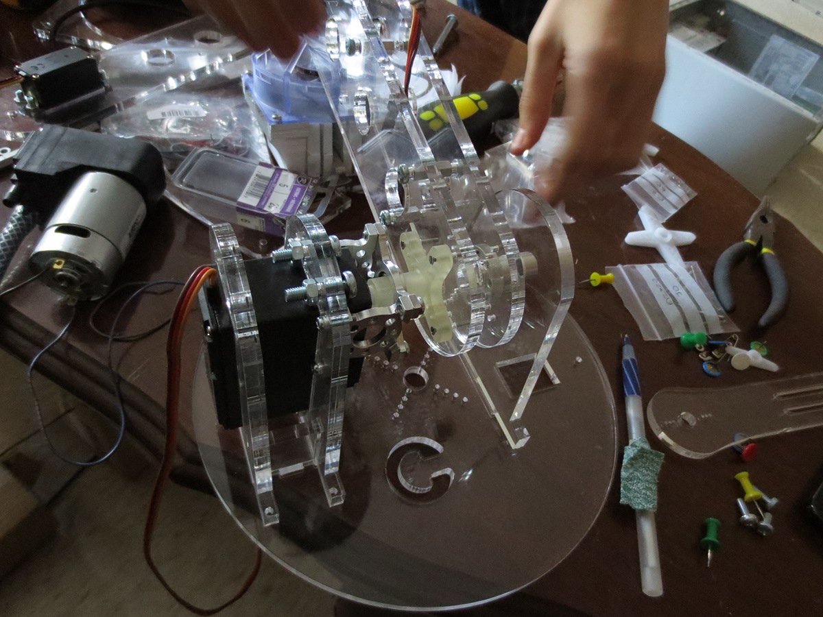
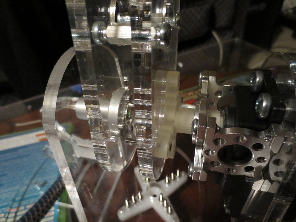
The 3D printed hub rotor fits in perfectly! (well almost, thank you sand paper!).
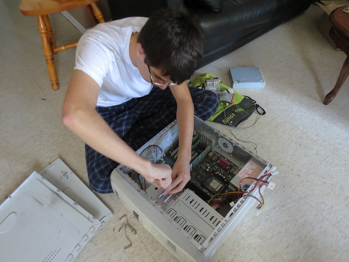
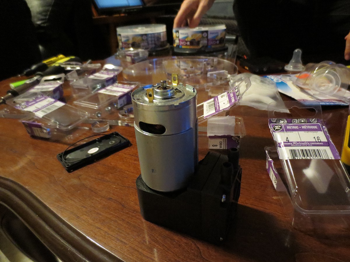
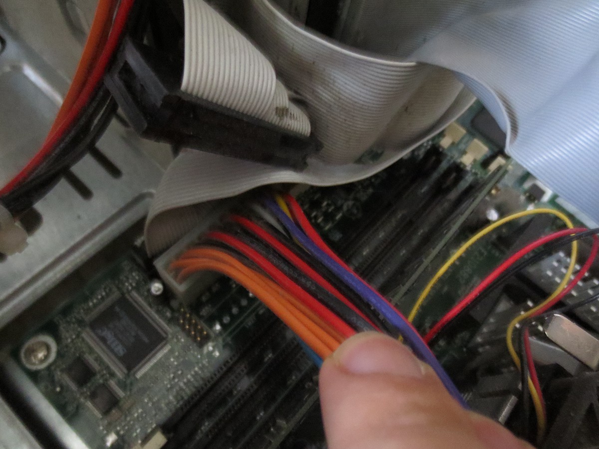
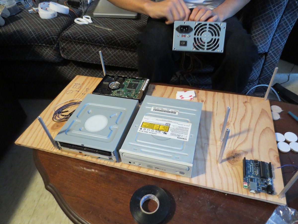
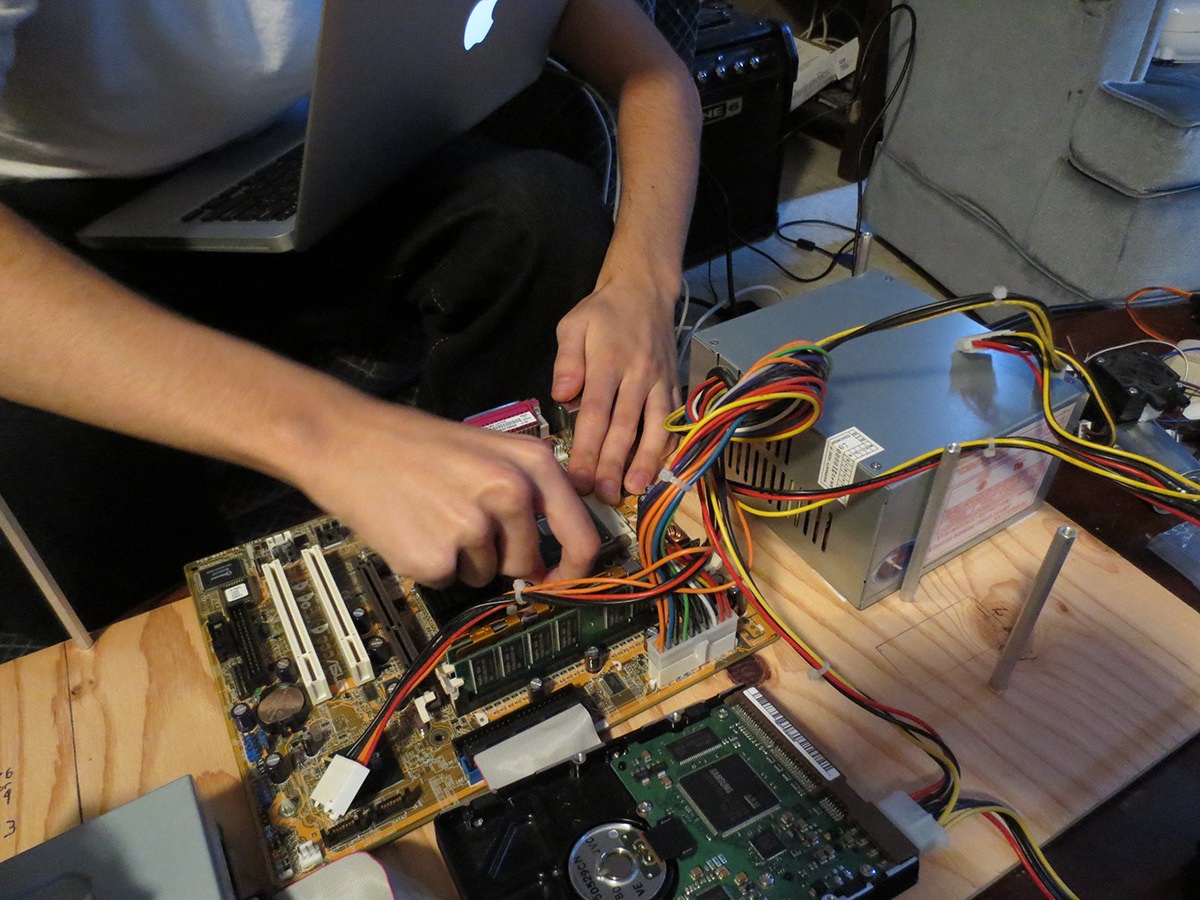
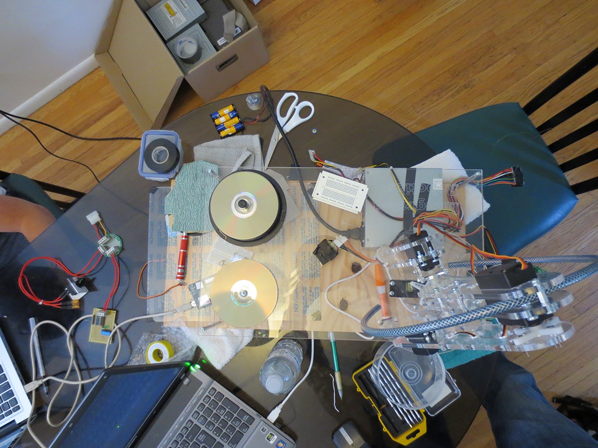
Looking through some old hardware that can be useful for our project.

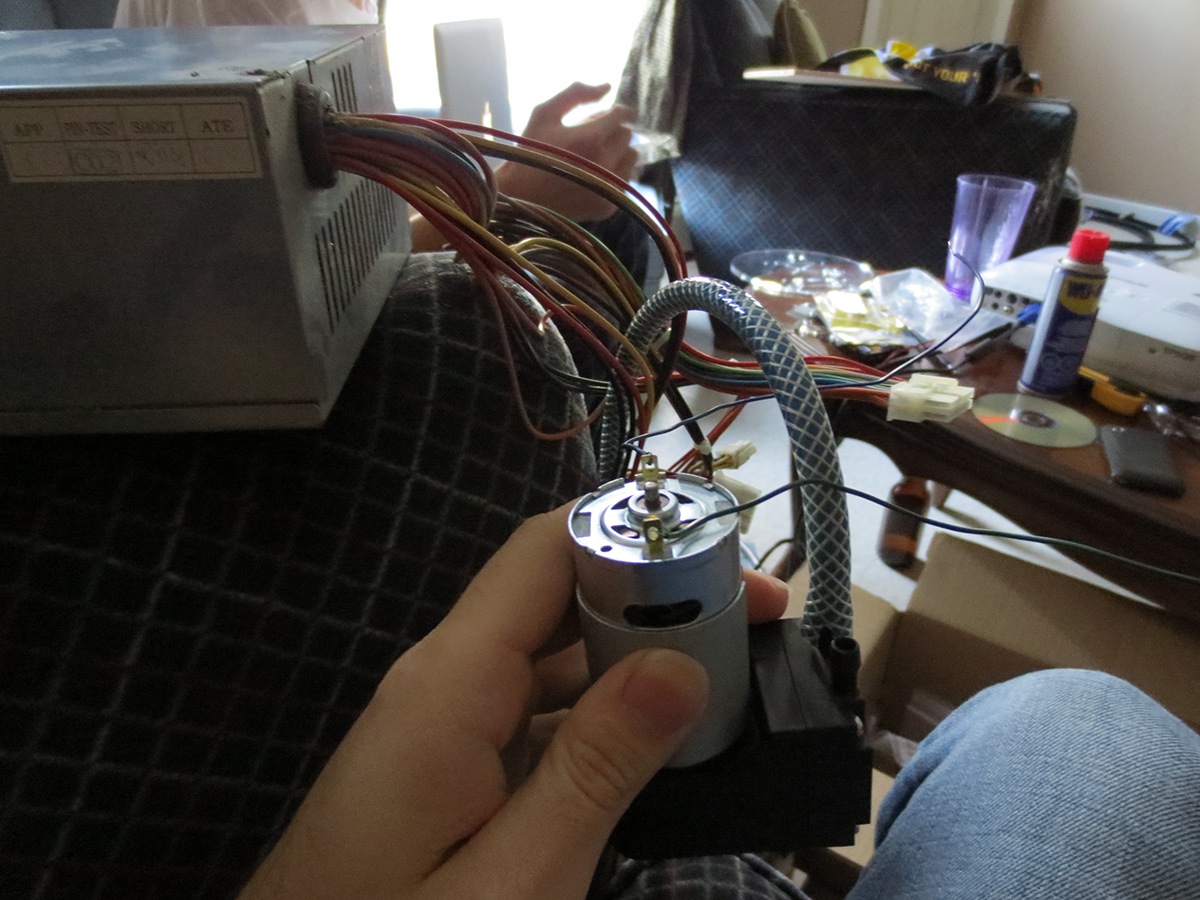
Attaching the 12 V power supply output directly to the vacuum pump, definitely too much suction.

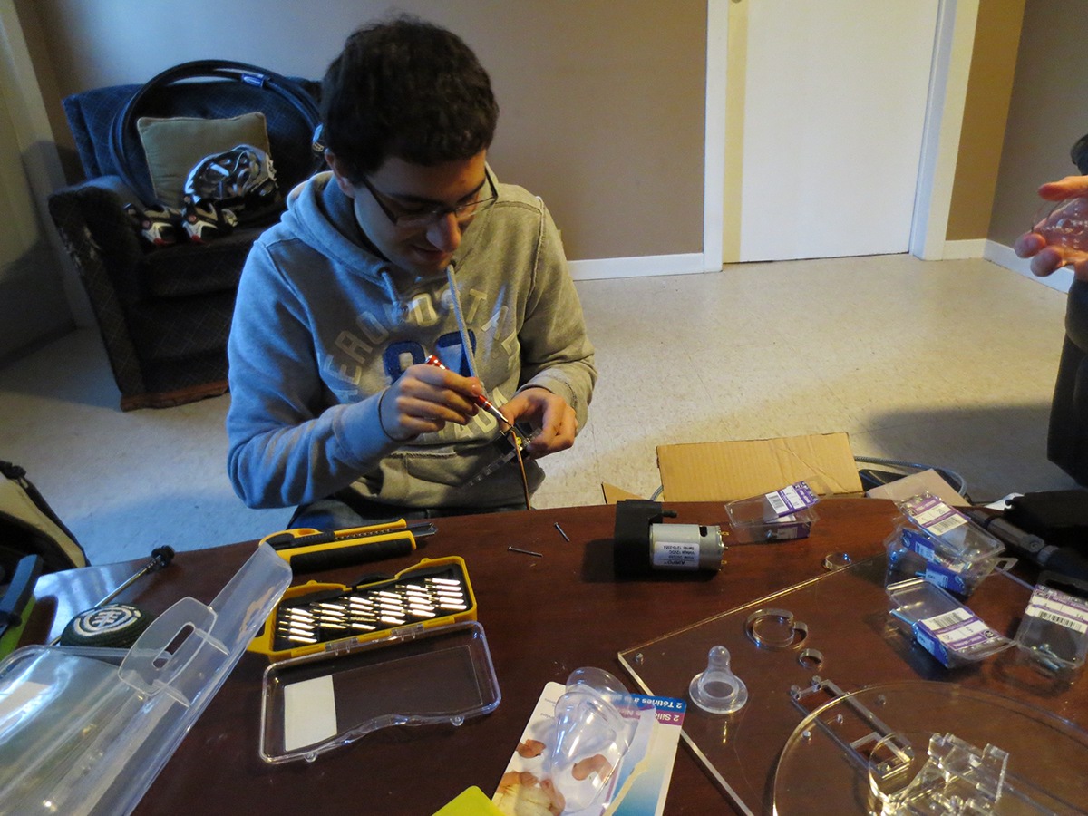
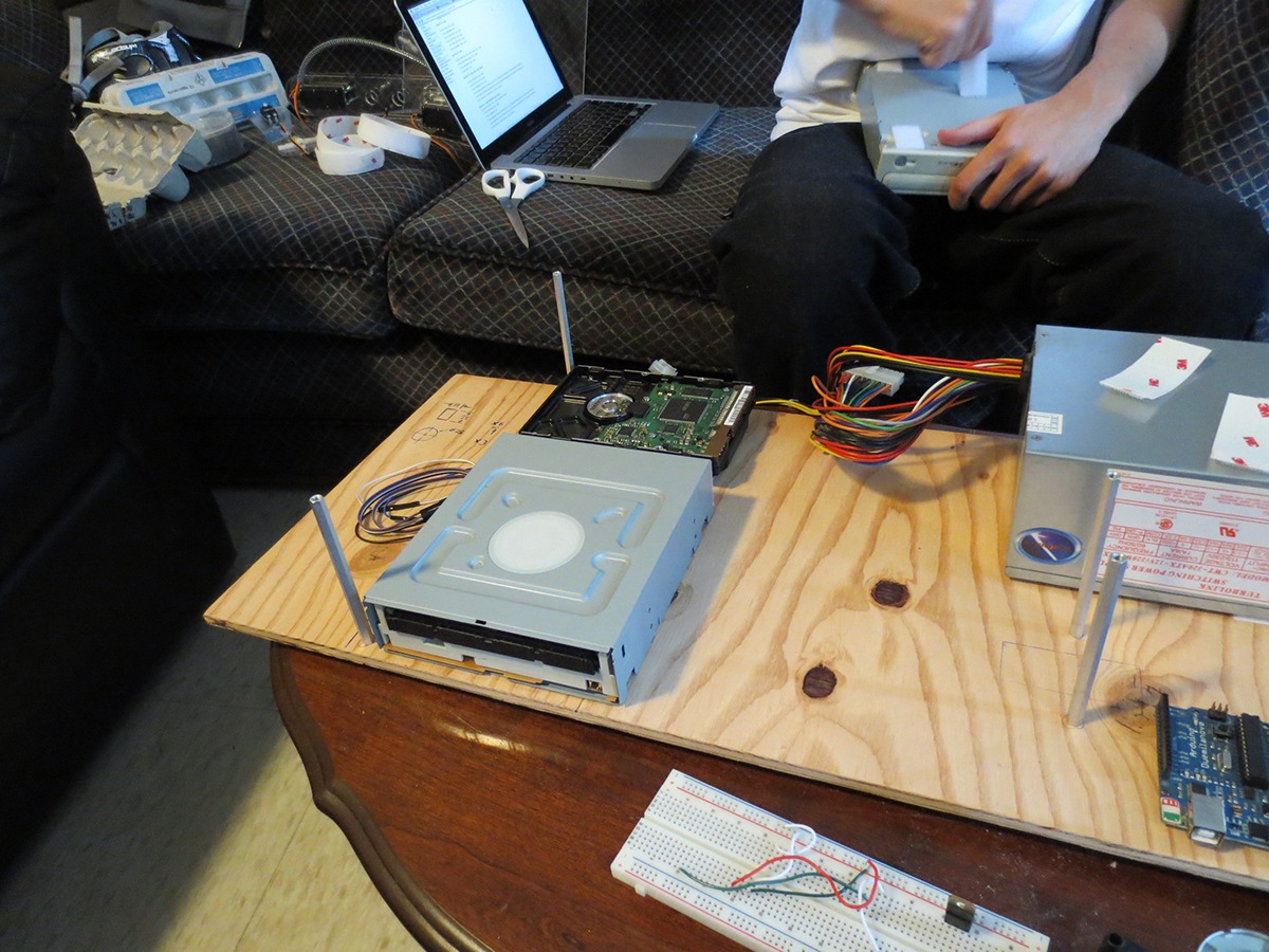
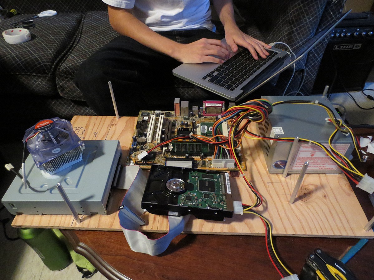
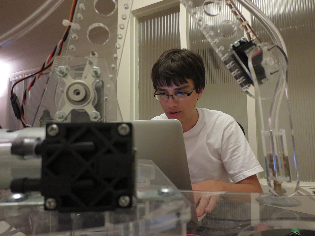
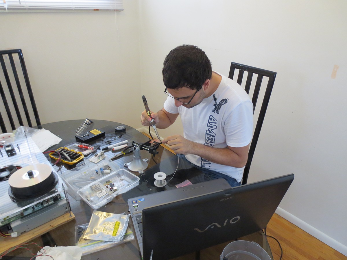
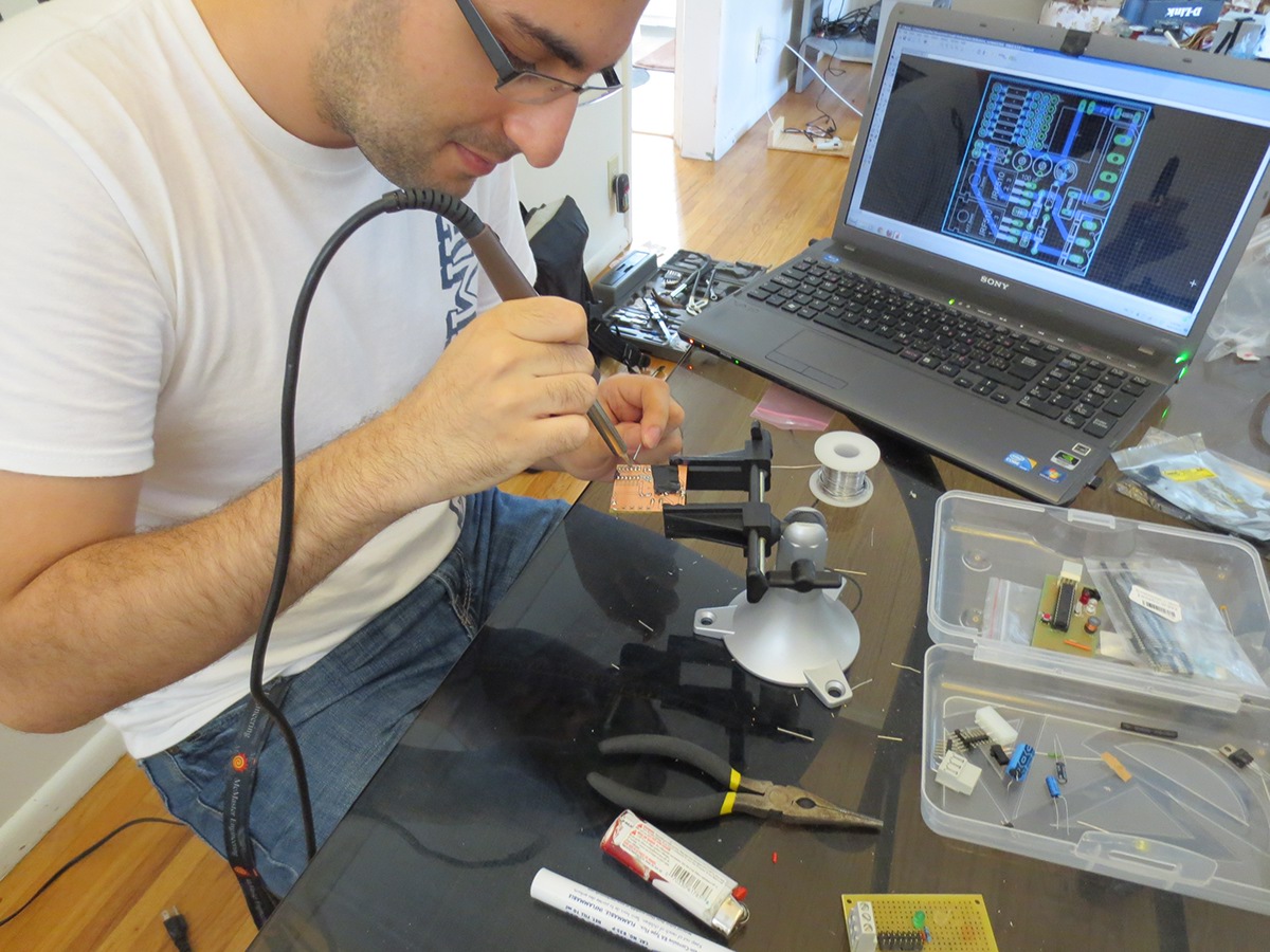
Paul, our most valuable programmer hard at work.
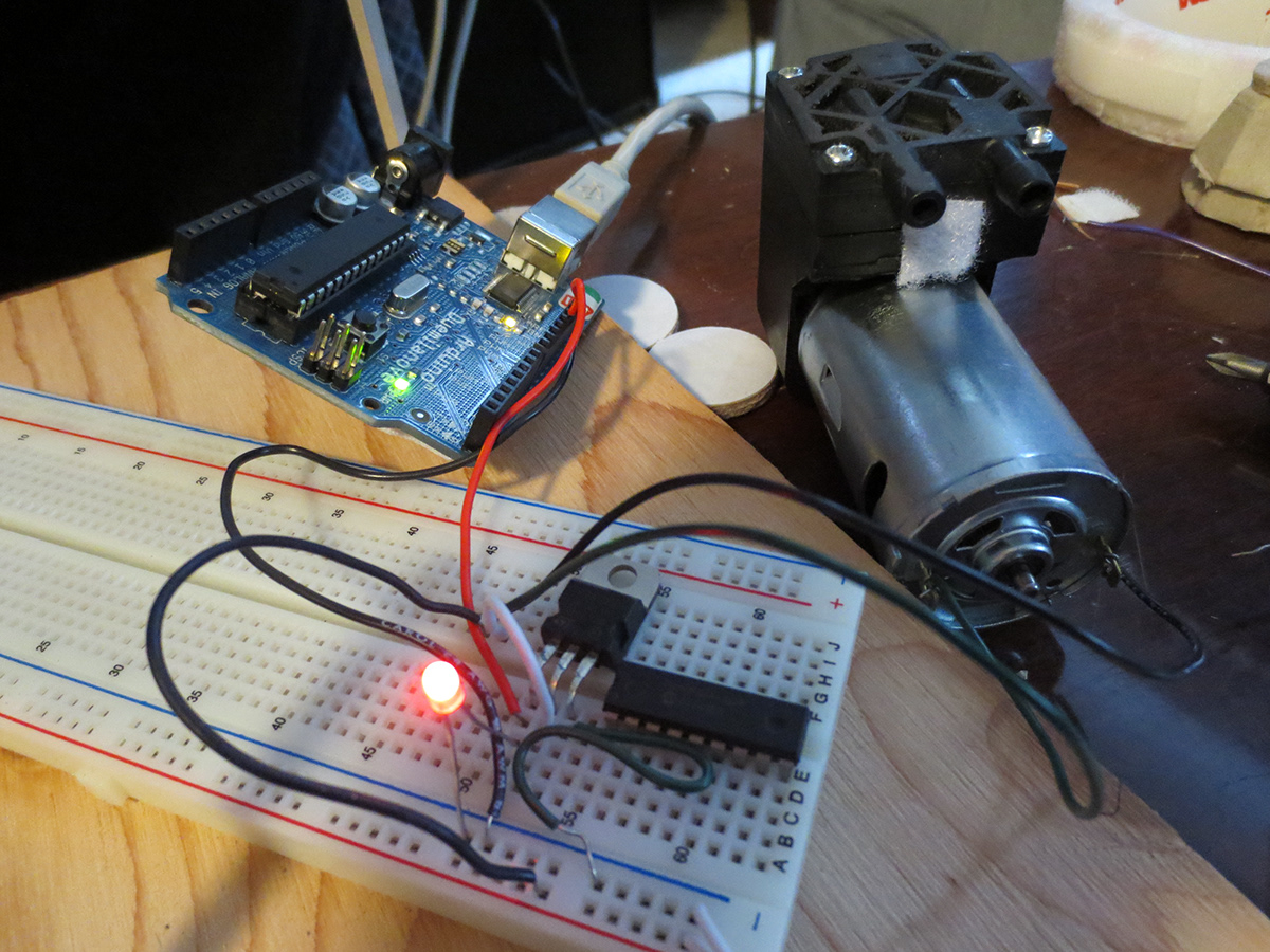
We successfully created a 5 V sinusoidal duty-cycle PWM output through the Arduino being fed into a 3.5 amp 1000 V mosfet to regulate the suction force from the pump, then we realized the mosfet's Gate-Source Voltage is 30 V, two of our members gave up on life shortly afterwards.
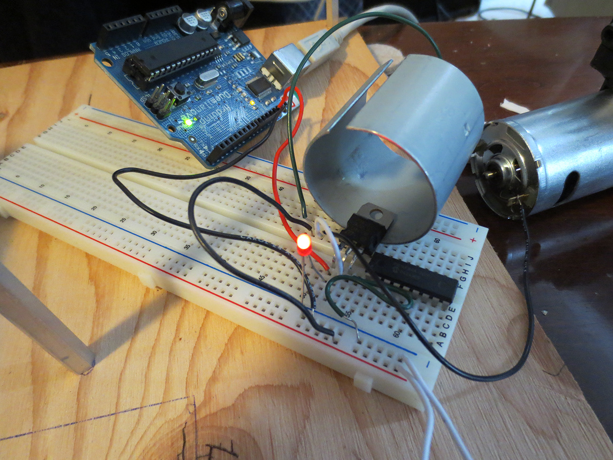
The vacuum pump's magnetic shield proved useful as a heat sink.
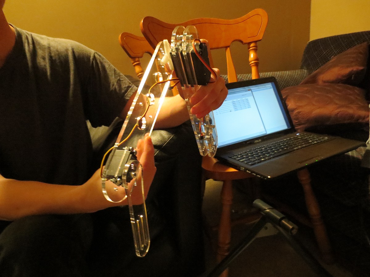
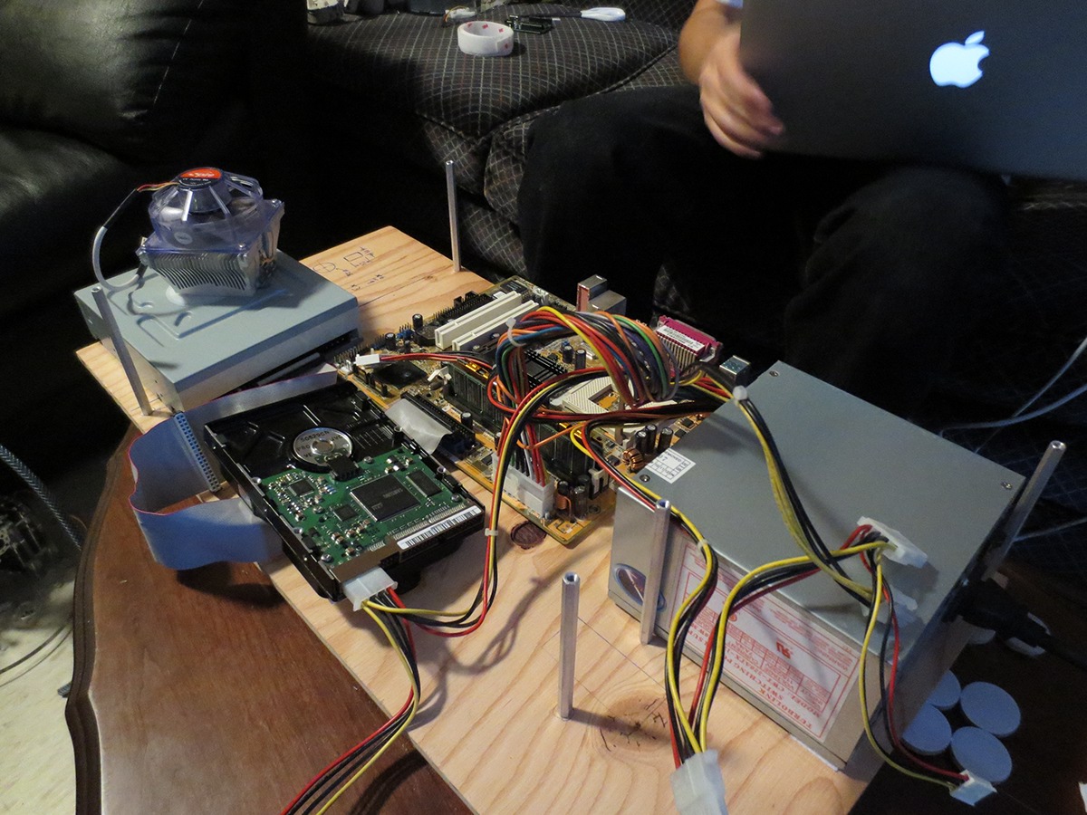
Hooking up the arm to a power supply, infinite energy!
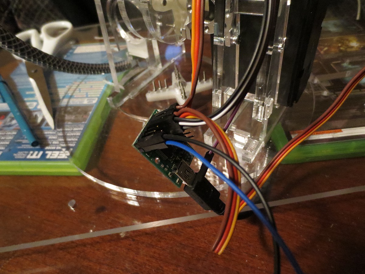
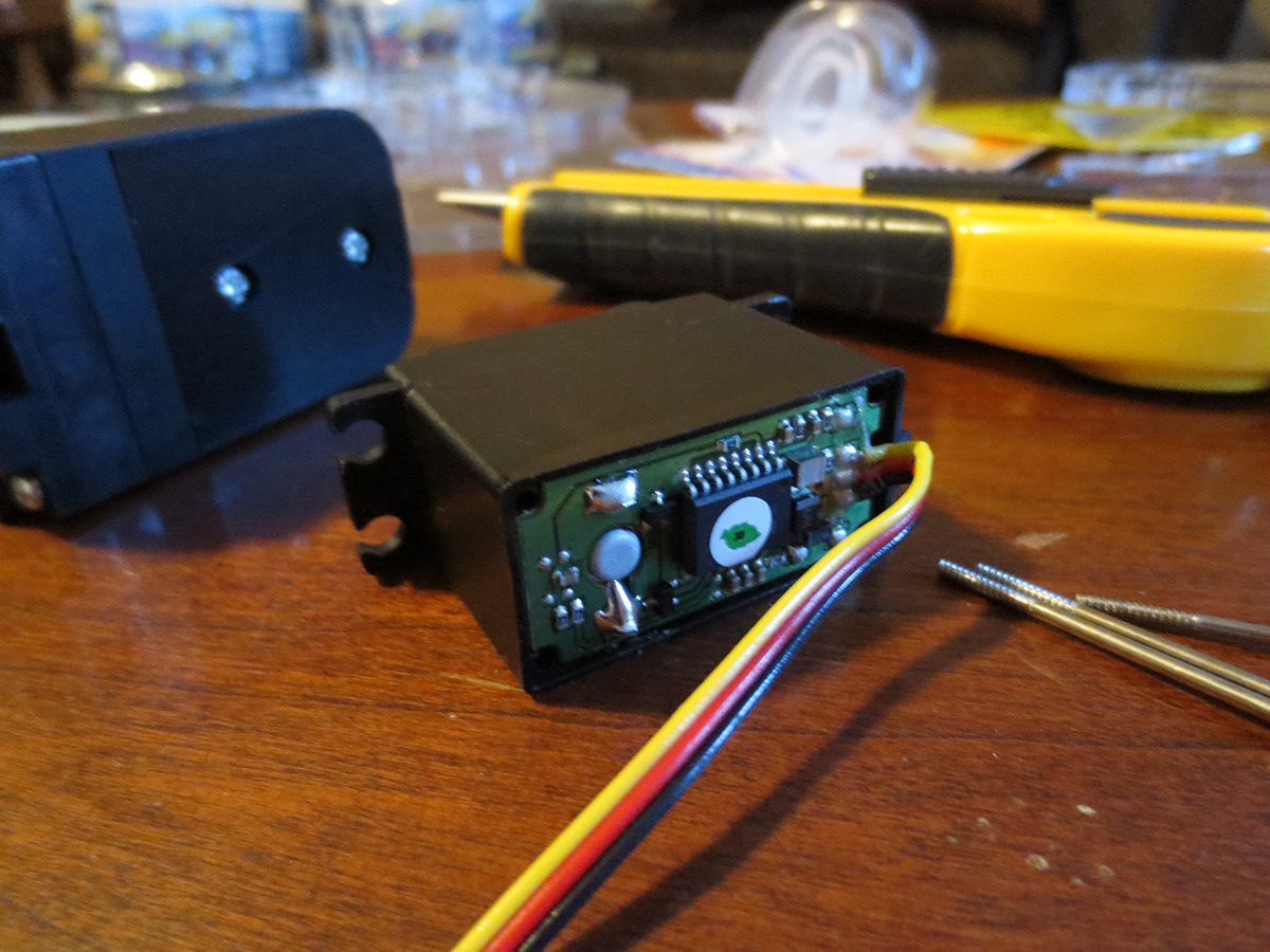
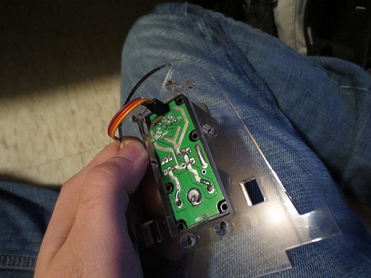
Servo controller.
LOOKS SO MECHANICAL!

An attempt at controlling the suction force of a vacuum pump using a pwm and a high current logic mosfet with no heat sink. Someone burnt their finger.
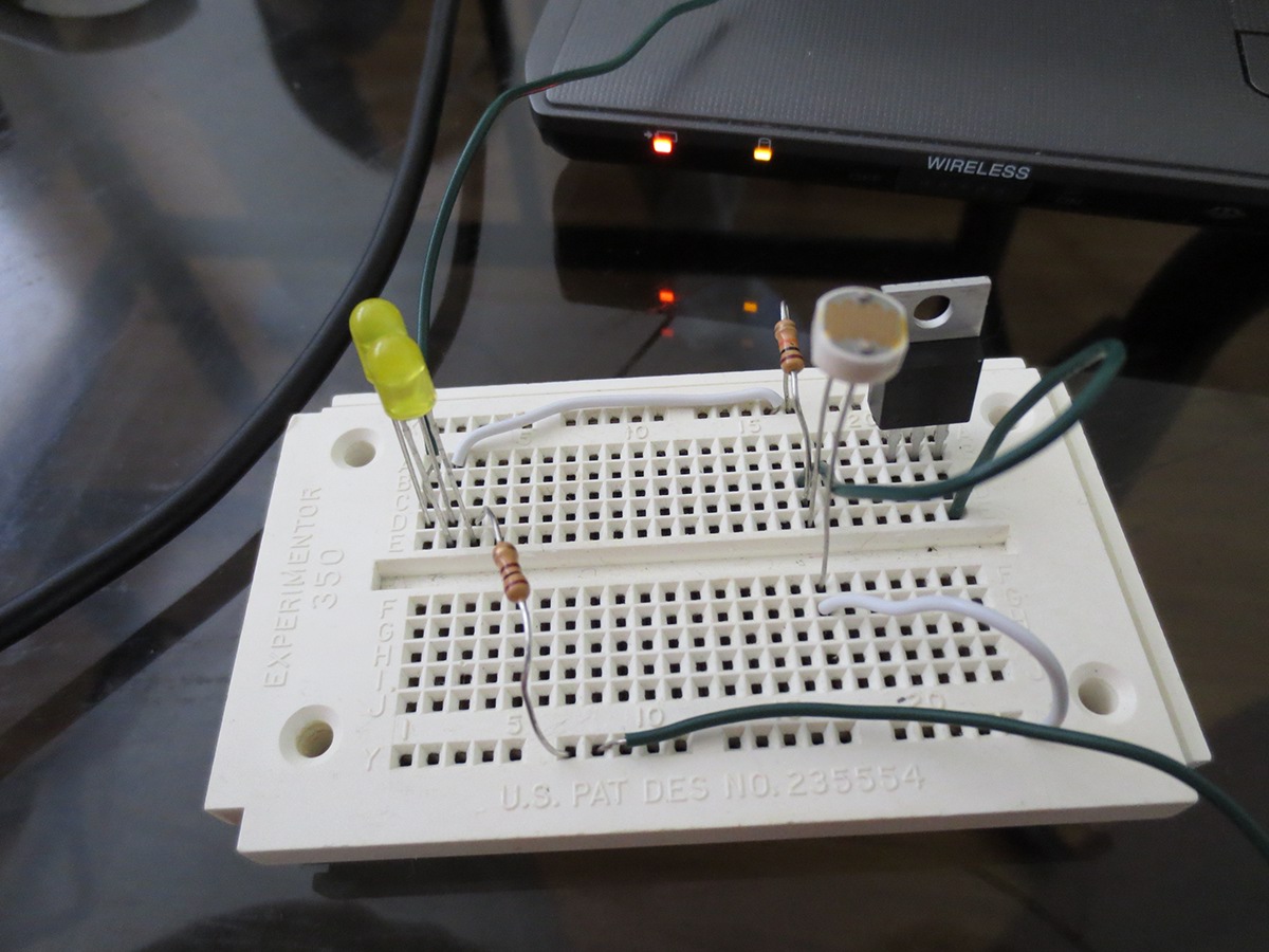
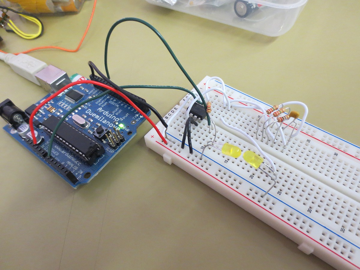
Testing out different light sensor circuits.
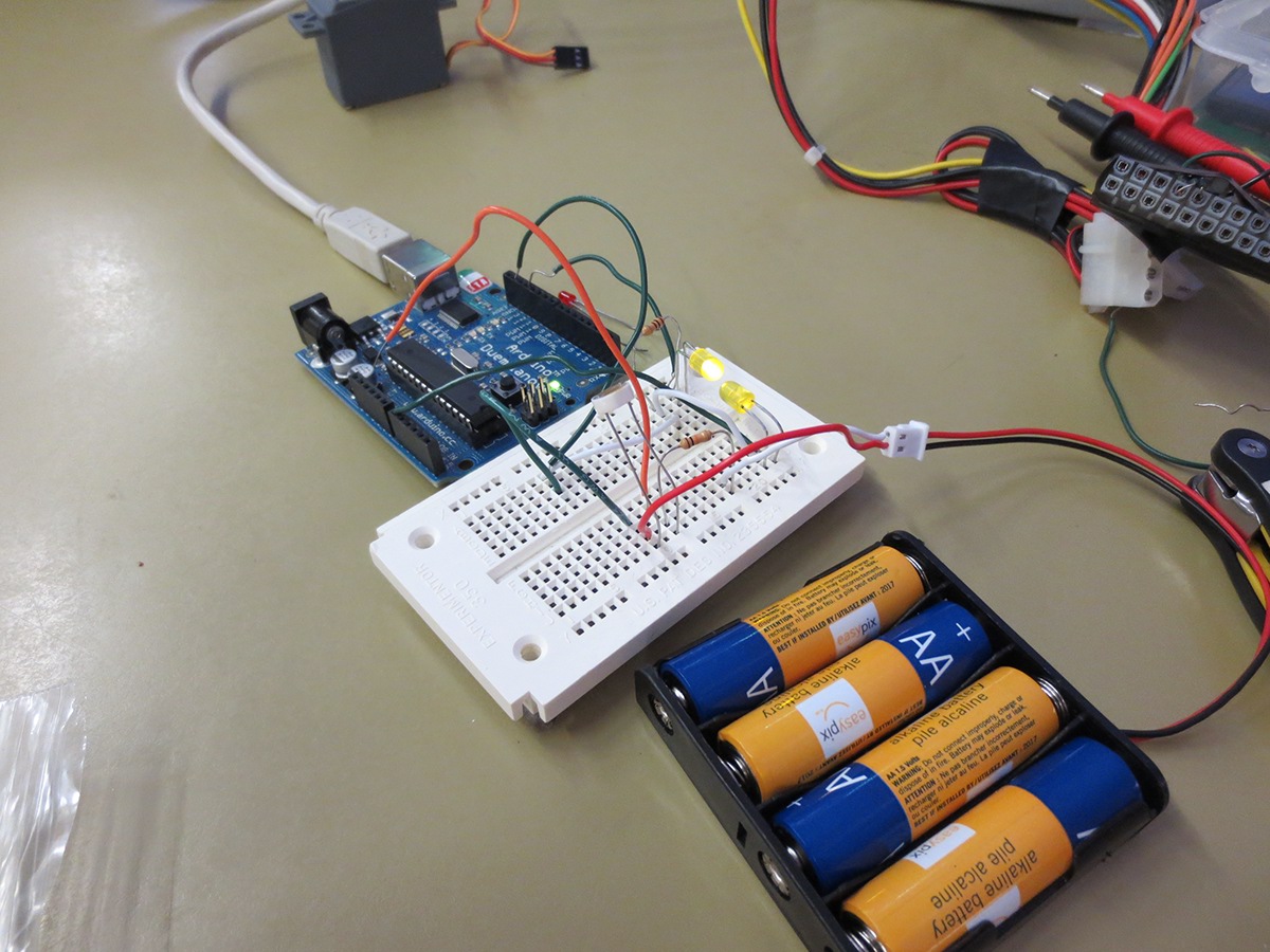
We attempted to read the analog value of a diode sensing light, we realized the light induced current is in the micro amps region and can't be measured by the Arduino. All the sampled data points were within the noise margin.
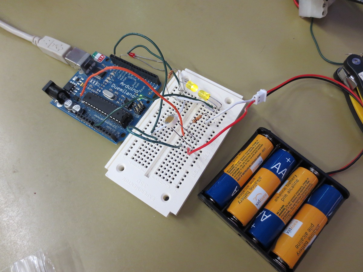
We also attempted to use a photocell to measure light. However, its reactivity is extremely slow and will not be effective in a pulsating light waveform.
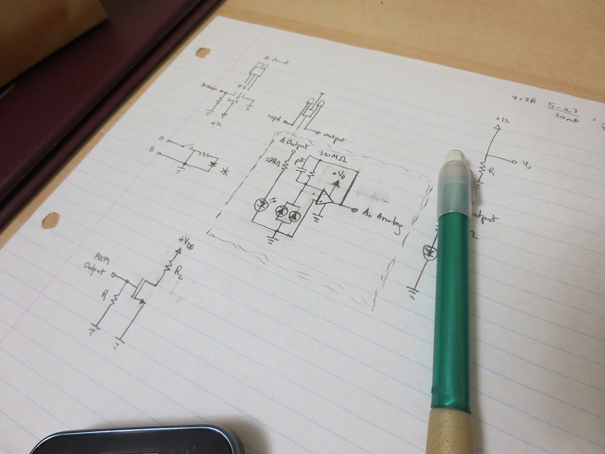
Designing circuits that amplify the signal from the light sensing diode.
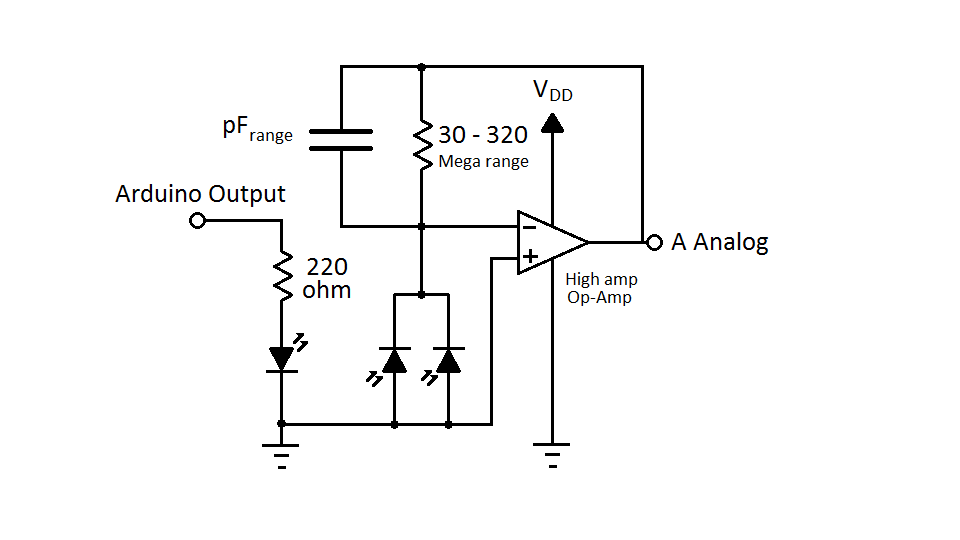
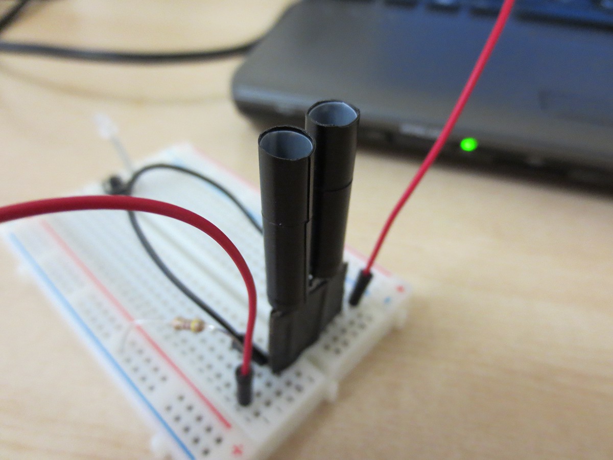
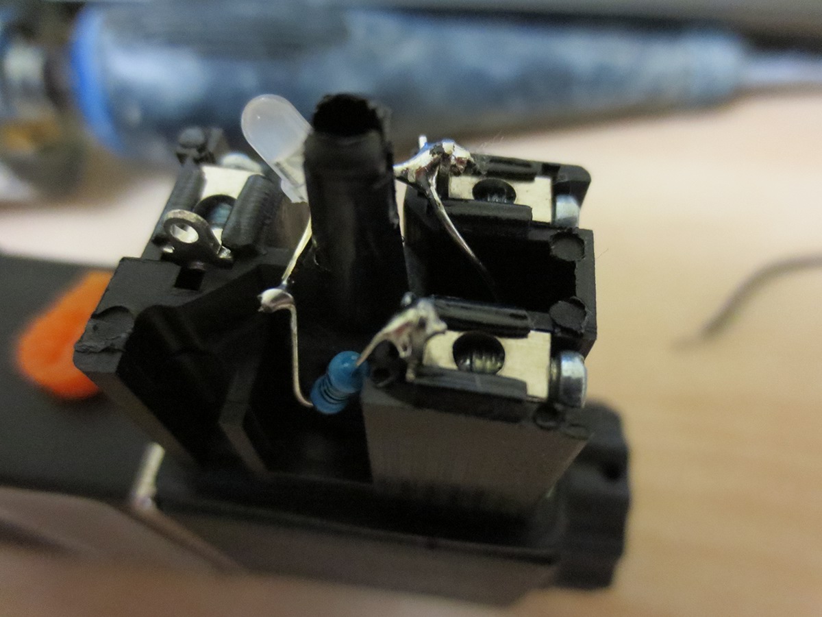
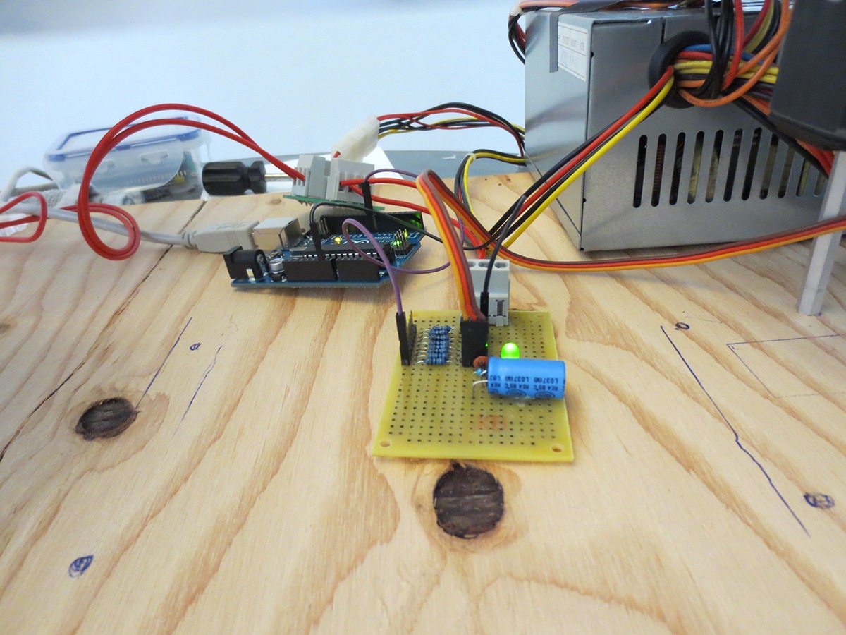
Light sensor circuit that we designed. It outputs pulses of light which reflect off the CDs and are measured by two LEDs in parallel. This lets the robot know when there are no CDs left in the stack.
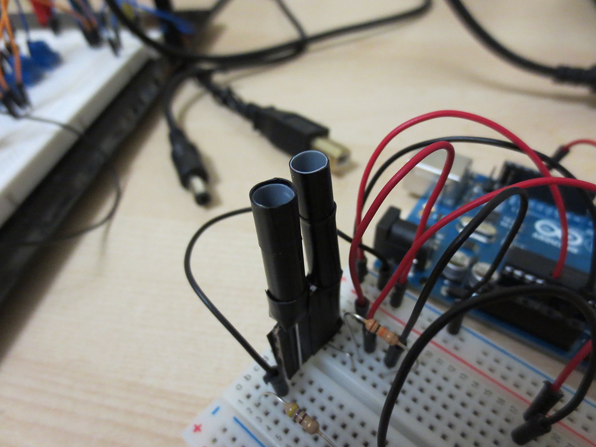
Building the Op-Amp light sensor circuit.
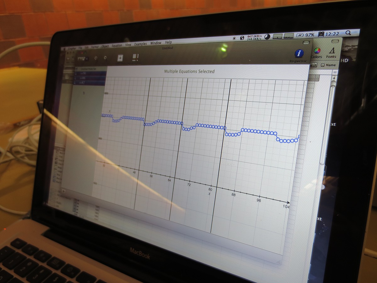
The op amp circuit significantly improved the signal, the actual square wave output being measured by the sensor is almost ideal to the input.
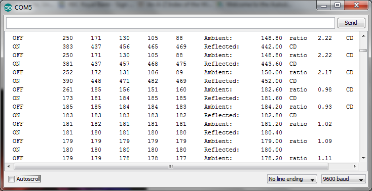
Serial communication between the sensor and a PC for debugging. We designed an advanced algorithm which adapts to the environment when measuring reflectivity. It can detect reflective surfaces in dark, normal and bright environments.
The Ambient variable displays ambient light measured, and reflective light measured for the reflected variable. The ratio variable is the ratio that the variable "reflective" must be relative to "Ambient" to distinguish between reflective and non reflective surfaces. The variable "ratio" changes its value accordingly, it decreases in bright environments, and increases in dark environments based on an inverse relationship we had developed.
"CD" is when the program detects a reflective surface between 20 to 150 mm.

Trying to control servos using an Arduino.
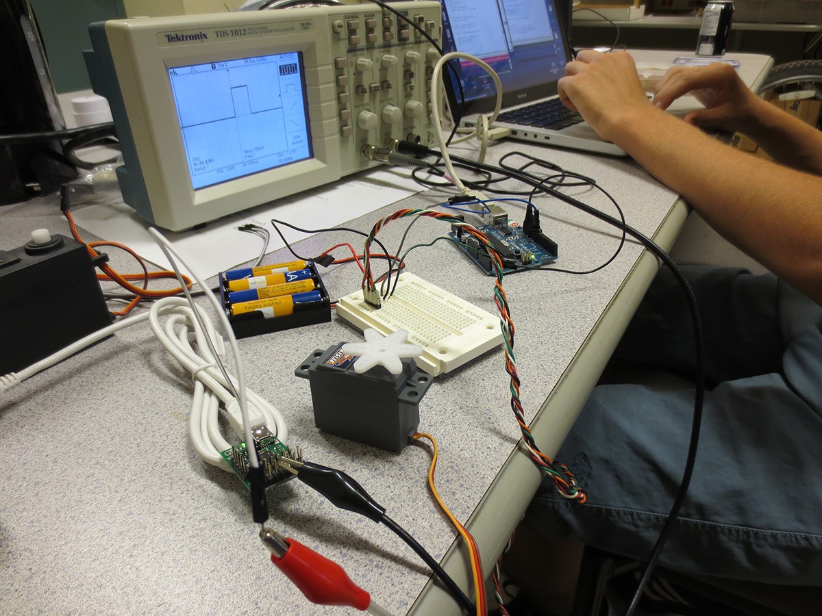
After hours of debugging with the oscilloscope (thanks to the IEEE office for letting us use theirs) and going through code, we successfully developed a serial data protocol to communicate with the servos using an Arduino.
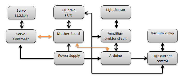
Control structure of the robot.
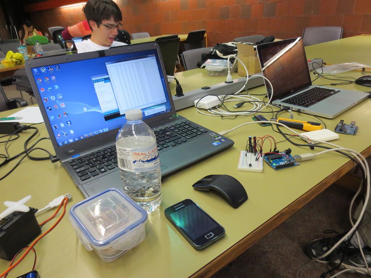
First time in human history had a Windows, Mac and a Linux engineer get together to build software.
Laser engraved Team Name.

Over-current protection circuit.
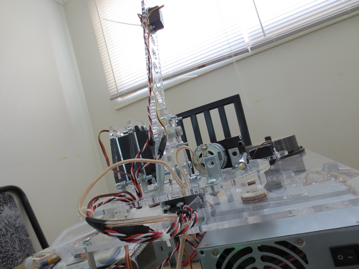
The jerky motion of the robot is caused by the heavy servo placed at the arm. Its angular momentum is too high and overshoots the specified angle which the base servo must reach.
Our submission deadline is two weeks from this point and we have decided to redesign the entire mechanical structure of the arm.
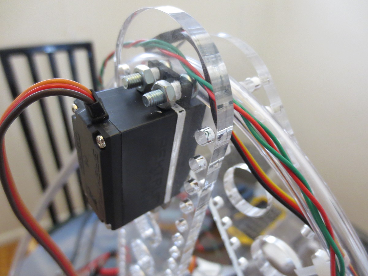
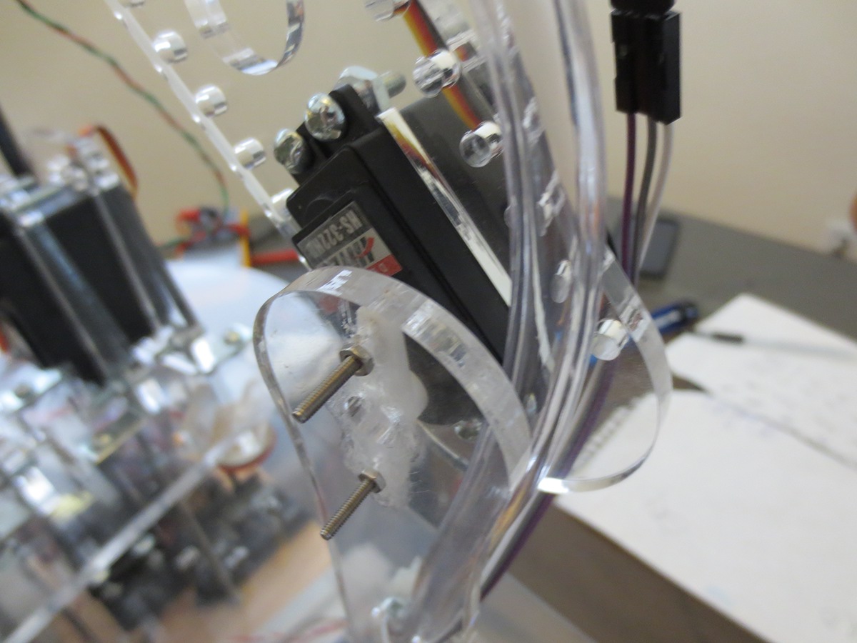
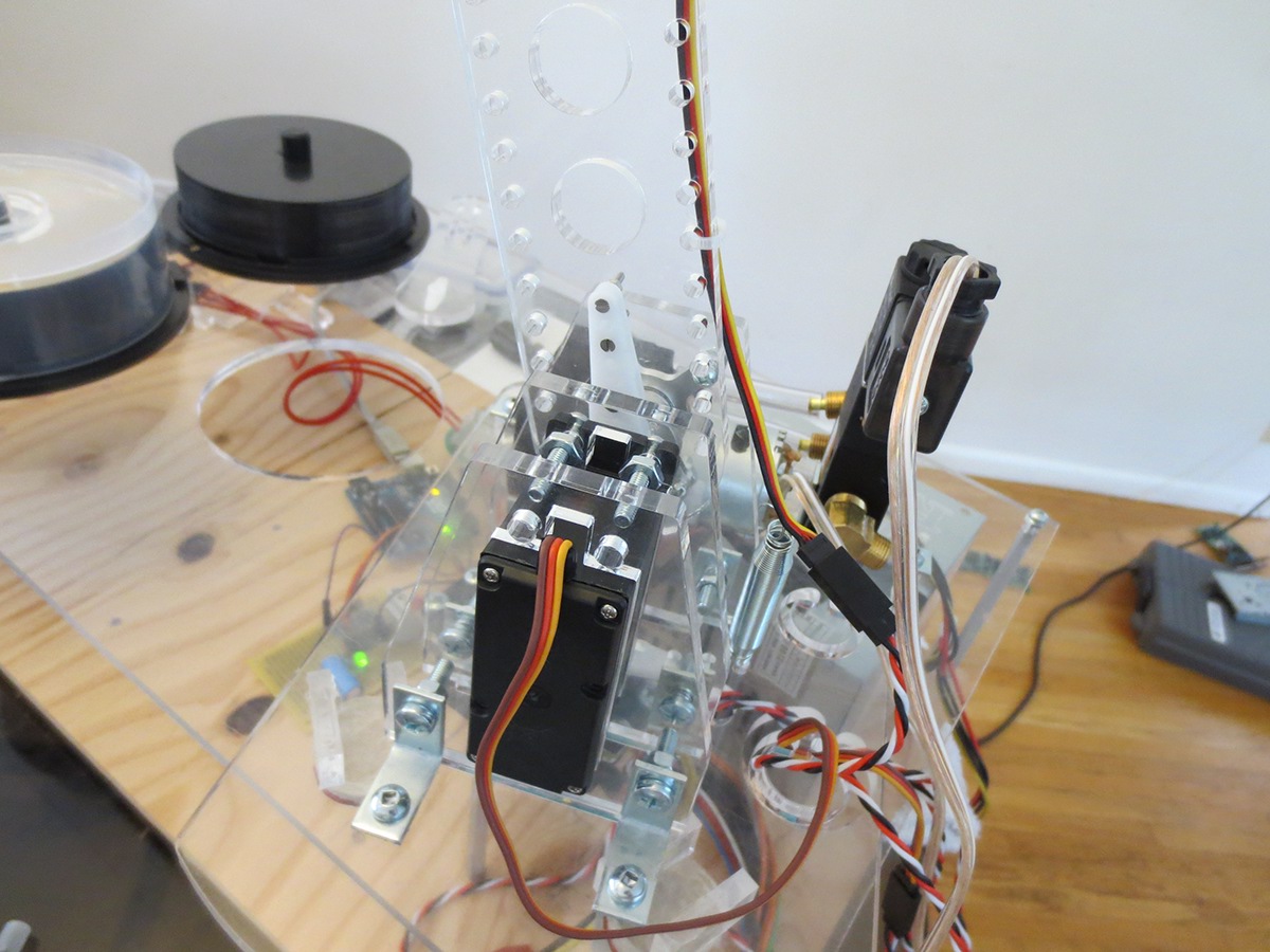
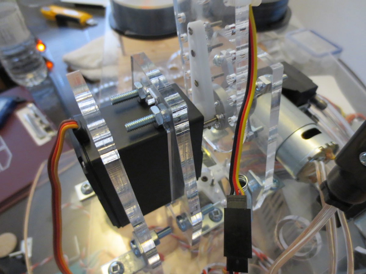
Our new arm design. Thinner, lighter, and contains a low mass to torque medium hobby servo (HS-322HD).
Multiple holes on the side of the arms lessen the weight, and gives us flexibility when adding zip ties to hold the wires, tubing and if we decide to add springs.

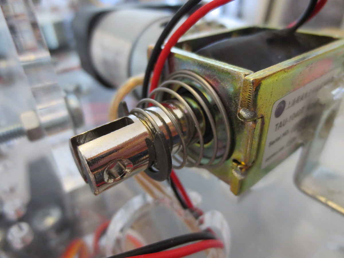
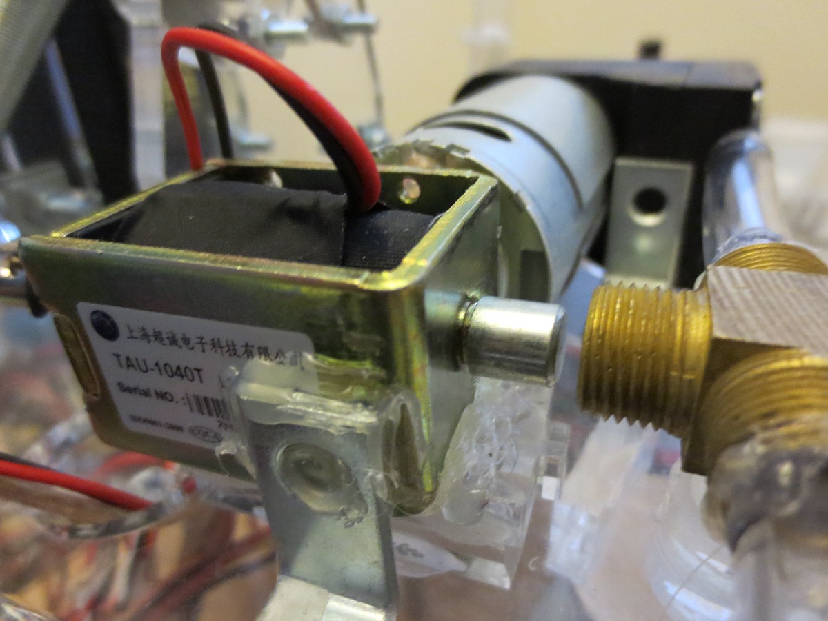
The solenoid has finally arrived. The solenoid valve is a 3 port network (on off on) which will allow us to electrically switch from suction to outflow.
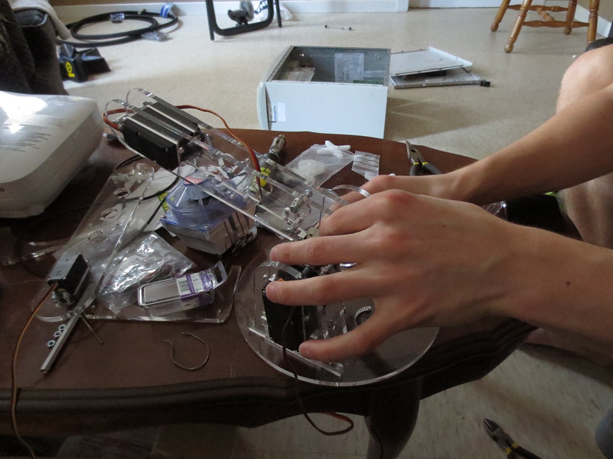
Assembling our new design.
L brackets for supports.


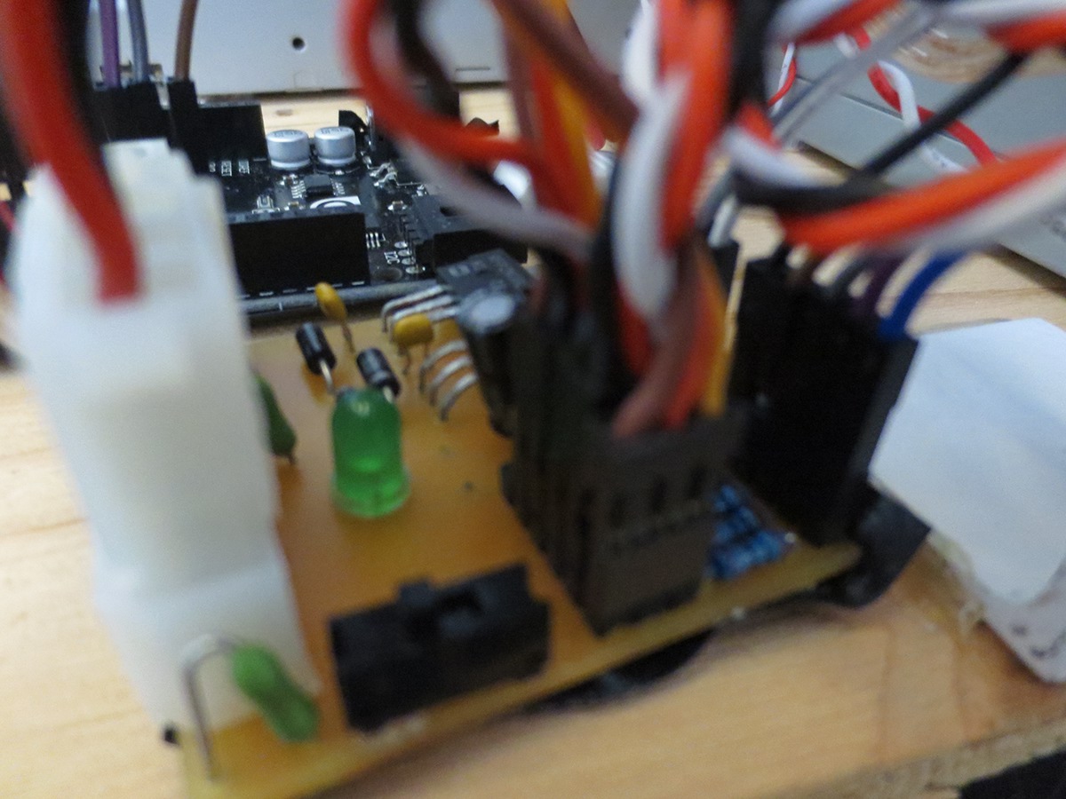
Arduino controller and the over current protection system.
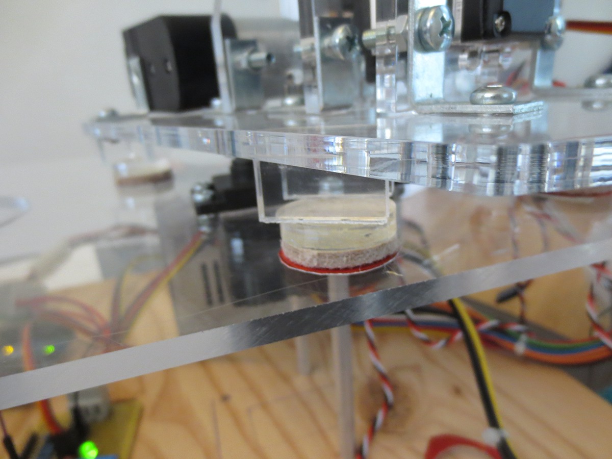
Mini shoes under the lazy Susan to distribute the force instead of keeping it concentrated on the servo spline.

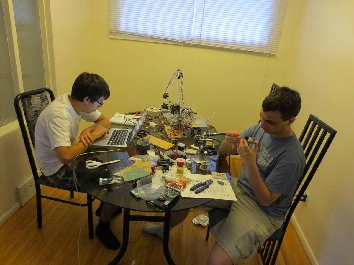
Acting like they are doing something.
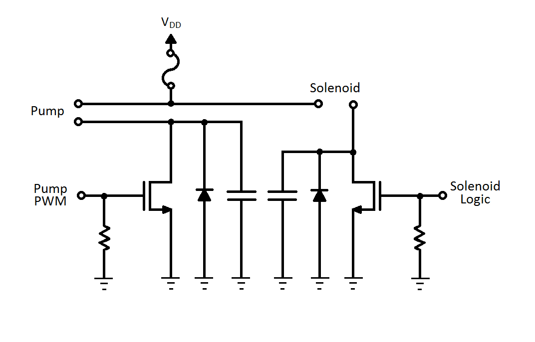
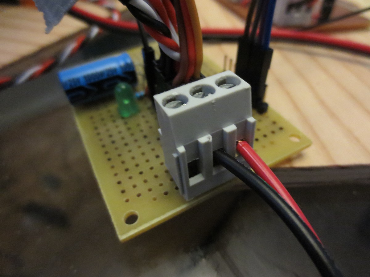
We needed to control 12 and 24 VDC 1+ A elements such as a solenoid and a pump using an Arduino. So we designed a logic control circuit that contains security features such as over current and reverse current protection.

The pump and solenoid release valve control and over current protection circuit.
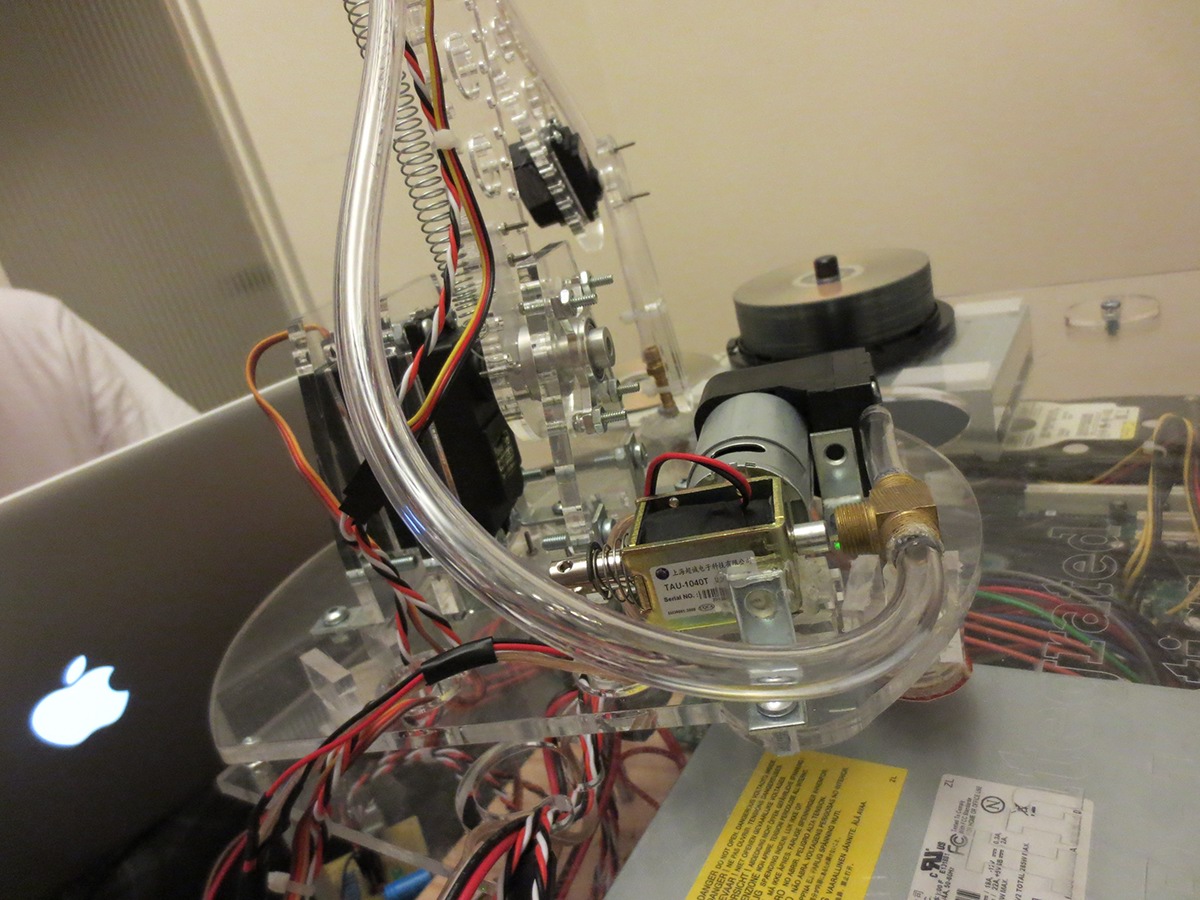
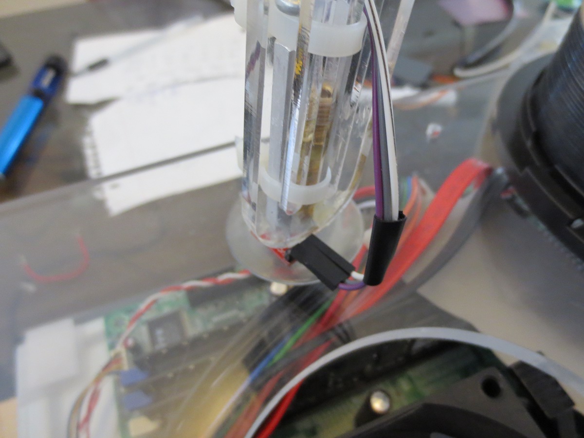
The solenoid is used as a pressure release mechanism to allow the objects to instantly drop off once the pin moves out of the T connector.


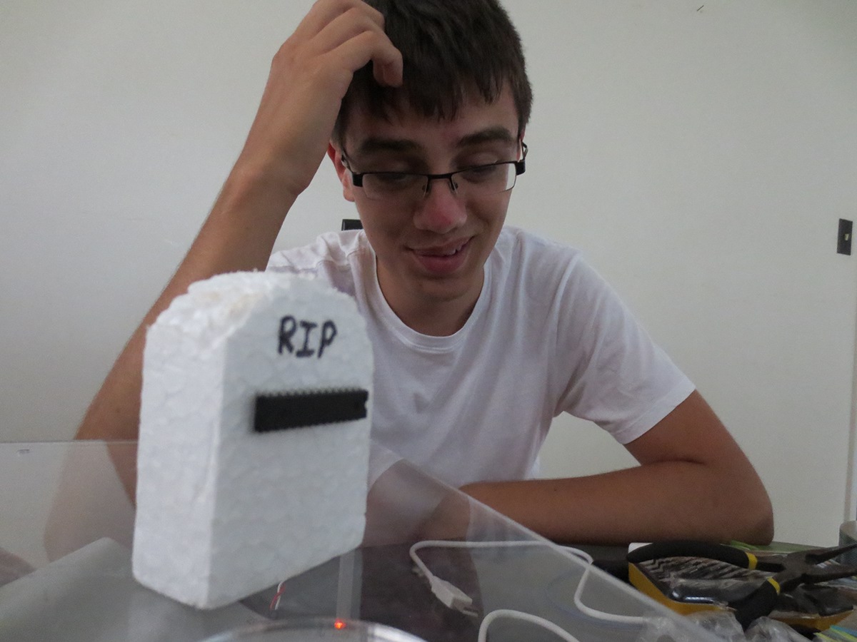
The AVR microcontroller of the Arduino Duemilanove that suffered a terrible death due to Paul's lack of hardware knowledge as he regularly states "I don't care about the hardware from the power input to the keyboard, all I care about is software".
Dear ATmega328, you have provided us with much help in developing our robot and your efforts will not go unnoticed, We will make sure that Paul learns his basics in electrical engineering before working in future projects. R.I.P. (Rip In Pieces... at the recycling factory!).
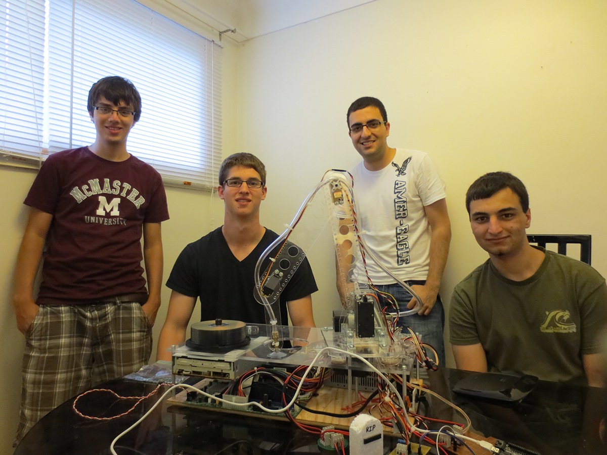
Group photo for the competition submission. From left: Paul Correia (Mechatronics Engineering), Drew Saltarelli (Mechanical Engineering), Mhamad Salih (Electrical Engineering), Tyler Delaat (Computer Engineering).

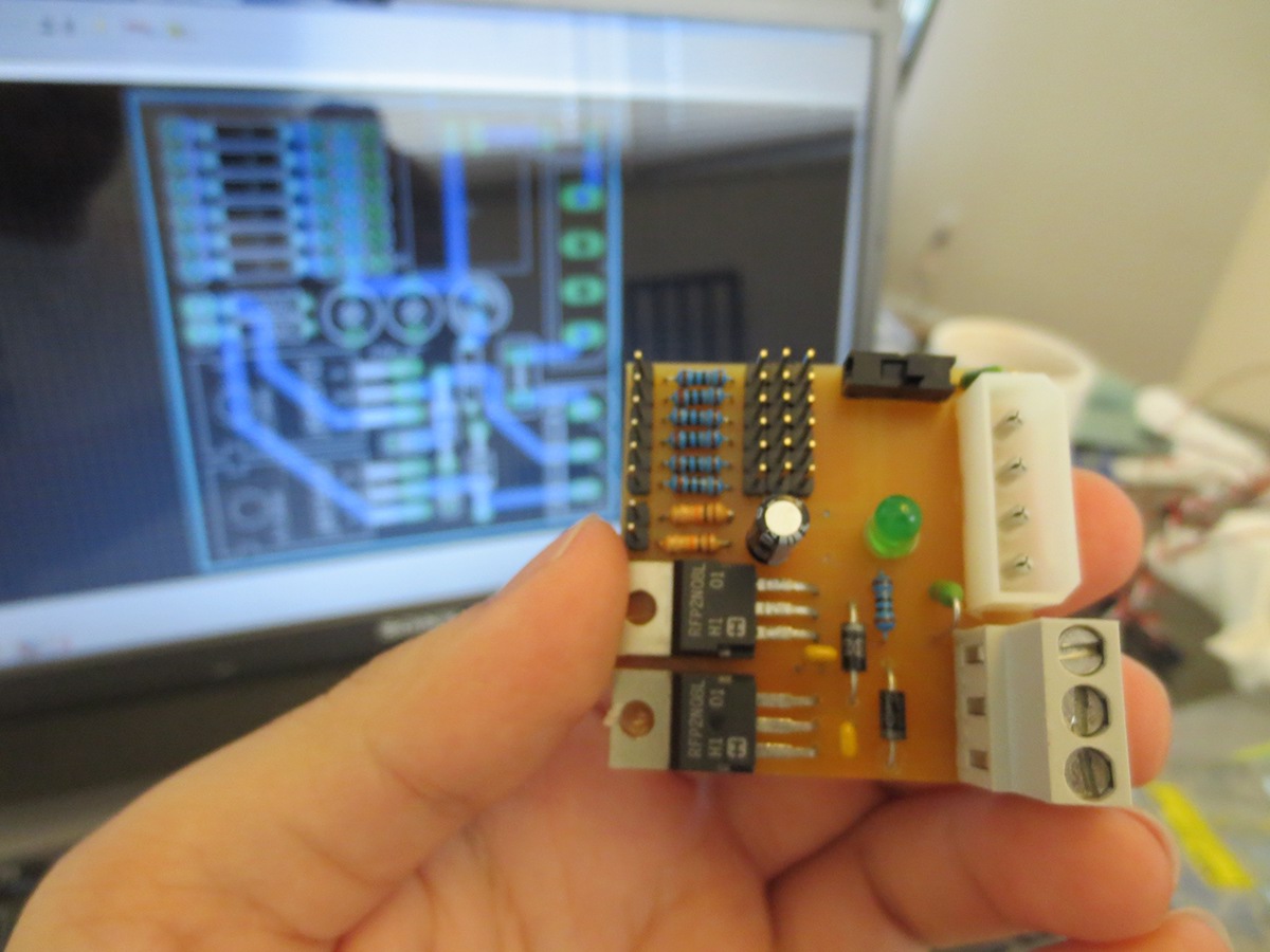
Designing a new circuit that will hold the servo control, solenoid control, noise filtration system, pump PWM and over current protection system. This will connect directly to the Arduino and its peripherals, acting as a link between the two systems.
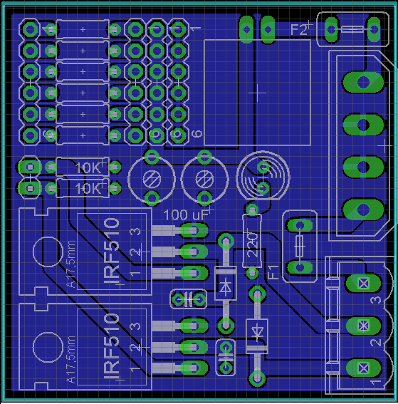
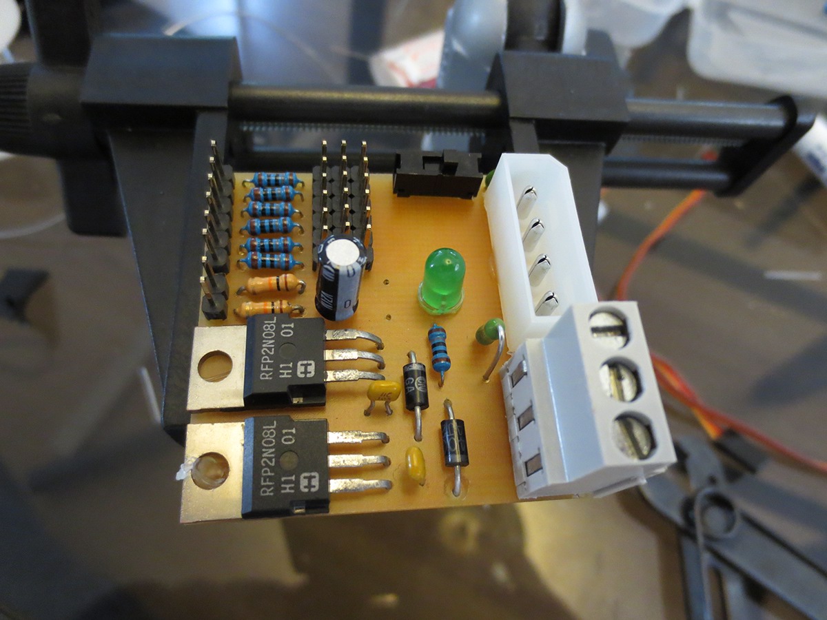
The Final board layout.
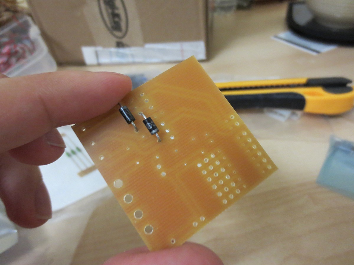
CNC Printed Circuit Board. (Special thanks to Matt Sheridan)


Sensor under the end effector for detecting CDs.