Design|Process Portfolio
A summary of procedure used in my studio practice
A summary of procedure used in my studio practice
This series begins with a collection of short photo essays describing techniques and processes that I use in the studio. It is not intended to be all-inclusive but simply to provide examples of how I approach my work.
Rotational casting
The rotational casting process is similar to a traditional slip casting except that the randomized motion designed to evenly coat the inner surface of the mold with the casting material has been mechanized. Two axes are arranged at right angles and so that one rotates within the other. With each axis running at slightly different speeds, a fairly random motion is produced that helps prevent any pooling or repeated pattern flows of the material as it cures and hardens. Unlike slip casting, a measure amount of material is poured into the mold at the beginning of the cycle all of which cures to form the final casting.
The rotational casting process is similar to a traditional slip casting except that the randomized motion designed to evenly coat the inner surface of the mold with the casting material has been mechanized. Two axes are arranged at right angles and so that one rotates within the other. With each axis running at slightly different speeds, a fairly random motion is produced that helps prevent any pooling or repeated pattern flows of the material as it cures and hardens. Unlike slip casting, a measure amount of material is poured into the mold at the beginning of the cycle all of which cures to form the final casting.
Hollow Cast Counterweight
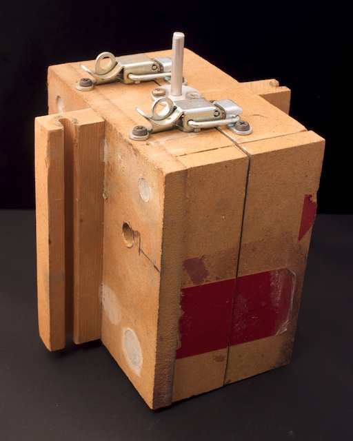
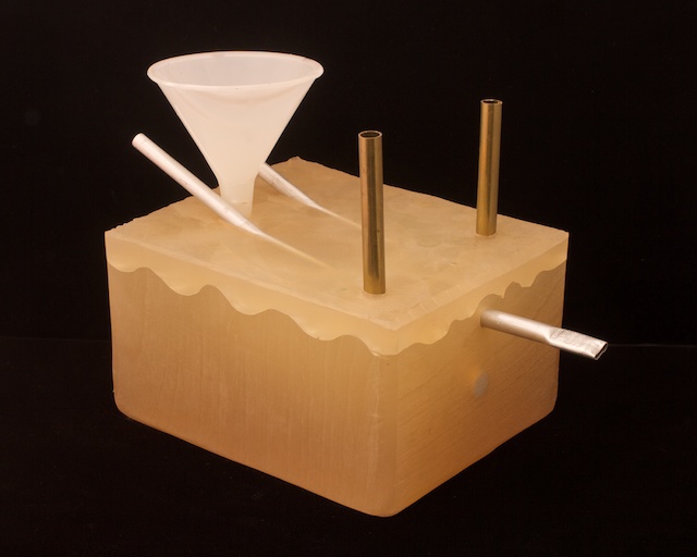
Mold BoxA mold box with mounting tabs for the rotational casting machine. The plaster fill material can be seen at the holes drilled into the box at various locations
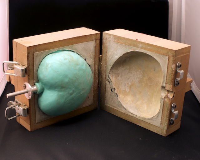
Opened ViewPlywood mold box with plaster support and silicone mold in place. The mold fill and mounting location can be seen at left. The mold was made by suspending the original pattern in the box by means of the rod running through the flange at left. With the pattern coated with a layer of clay, the plaster was poured into the remaining cavity through holes in the plywood support box. The clay was then removed, allowing the silicone to be poured into the resulting cavity. The mold was then wavy cut to release the pattern in preparation for casting the first part. This is just one of many ways of making a mold for this process.

Rotational Casting Machine
Shop built rotational casting machine with semi-randomized two-axis motion. The mold box is shown mounted and balanced for casting operation. A fabricated slip-ring allows for carrying current to the inner motor drive through the outer drive rotational axis. A pair of DCPM gear motors are used to drive the two axes. An adjustable counterweight compensates for the mass of the inner drive motor. A speed controller and reversing switch reside in the control box. This machine was built exclusively with materials at hand; steel from other tool or machine projects, a control box from the electrical salvage, motor controller and motors from earlier camera design projects, aluminum tubing and connectors from a large cage build for my African Grey parrot - these and some other miscellaneous scrap dictated the design of this machine. It proved to be pretty successful. The only thing I might change would be to increase the ratio at the toothed drive belt stage since the ratio in the gear motors leave little room to go as slow as I might like.
Shop built rotational casting machine with semi-randomized two-axis motion. The mold box is shown mounted and balanced for casting operation. A fabricated slip-ring allows for carrying current to the inner motor drive through the outer drive rotational axis. A pair of DCPM gear motors are used to drive the two axes. An adjustable counterweight compensates for the mass of the inner drive motor. A speed controller and reversing switch reside in the control box. This machine was built exclusively with materials at hand; steel from other tool or machine projects, a control box from the electrical salvage, motor controller and motors from earlier camera design projects, aluminum tubing and connectors from a large cage build for my African Grey parrot - these and some other miscellaneous scrap dictated the design of this machine. It proved to be pretty successful. The only thing I might change would be to increase the ratio at the toothed drive belt stage since the ratio in the gear motors leave little room to go as slow as I might like.
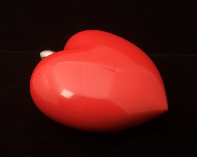
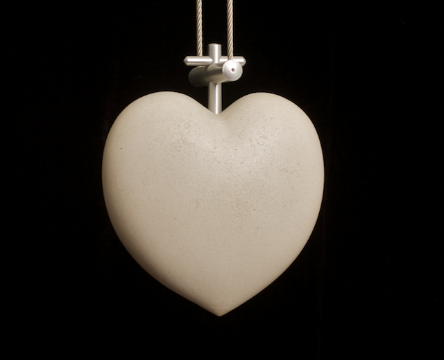
A Finished CastingA sample casting in urethane resin with lacquer finish. This object takes additional advantage of the hollow shapes resulting from rotational casting. Since the plaster version above serves as a counterweight for the Matterhorn luminaire design, the opening at the top can be used to introduce an appropriate amount of ballast (sand in this case) for the weight to function properly. The final part was create with a casting plaster.
Urethane casting
This is the traditional poured casting method in which the material (urethane resin in this case) is poured into a prepared mold using techniques intended to prevent the formation of bubbles or voids in the final casting. In this particular project, there were various inserts required to provide mechanical mounting locations in the final casting. A semi-transparent silicone mold material was used to facilitate the accurate initial cutting of the mold and the subsequent management of the inserts.
This is the traditional poured casting method in which the material (urethane resin in this case) is poured into a prepared mold using techniques intended to prevent the formation of bubbles or voids in the final casting. In this particular project, there were various inserts required to provide mechanical mounting locations in the final casting. A semi-transparent silicone mold material was used to facilitate the accurate initial cutting of the mold and the subsequent management of the inserts.
The Completed Mold
Silicone mold with wavy cut line and multiple inserts for placing components and filling the mold.
Silicone mold with wavy cut line and multiple inserts for placing components and filling the mold.

Opened Mold
Opened mold showing inserts and the wavy index cut line. This mold was made in a single silicone pour and then cut apart using a technique intended to keep a fairly straight cut at the part while inducing a wavy pattern at the outside edge. This allows the mold to index when put back together. A single larger fill hole and two smaller vent holes can be seen in the top of the mold.
Opened mold showing inserts and the wavy index cut line. This mold was made in a single silicone pour and then cut apart using a technique intended to keep a fairly straight cut at the part while inducing a wavy pattern at the outside edge. This allows the mold to index when put back together. A single larger fill hole and two smaller vent holes can be seen in the top of the mold.
Finished Part - Rear View
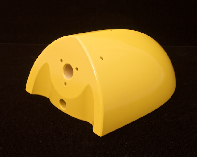
A part pulled from the mold showing as-cast insert locations plus machined holes. With lacquer finish awaiting hand rubout.
A part pulled from the mold showing as-cast insert locations plus machined holes. With lacquer finish awaiting hand rubout.

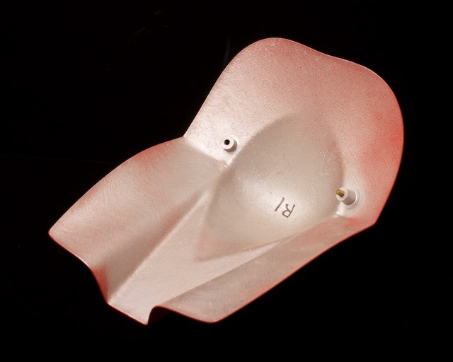
Finished Part - Front View
Front view of same part. Lacquer finish is rubbed out by hand from this stage. The catalyzed primer coat was the first pour into the mold followed after cure by the urethane casting material. The final finish was spray-applied out of the mold.
Front view of same part. Lacquer finish is rubbed out by hand from this stage. The catalyzed primer coat was the first pour into the mold followed after cure by the urethane casting material. The final finish was spray-applied out of the mold.

Finished Part - Inside viewUnderside view showing mechanical cavity, installed electrical inserts, additional insert locations and cast foot mount locations. The design calls for a small gearhead/stepper motor to be installed in the cavity for the purpose of animating this kinetic light sculpture called "Samurai".

Vacuum EquipmentShop built vacuum degassing machine for working with silicones, urethanes and other casting materials. And integrated vacuum pump operated by embedded controller. Mixed mold and casting materials with mechanically introduced air bubbles are placed into this machine to remove the gas from the mixture before making a pour. The control allows control of cycle time and will ultimately control introduction of atmospheric pressure at the end of the cycle. There is also a small compressor in the system for introducing a relatively low pressure into the chamber for specific application - also operated by the embedded controller.
Composites fabrication
Various traditional composites fabrication techniques are employed including this variation on the standard hand layup process. This silicone skin mold is easier to part from the completed work than a typical composite mold structure. A composite mother mold provides rigid support to the silicone mold during the laminating process.
This sequence illustrates the making of a "shade" component for the Samurai luminaire.
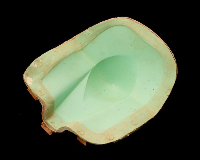
Silicone Skin MoldA silicone mold for laying up the composite cloth and resin part. This can be used either with hand layup techniques are in conjunction with a vacuum bag for producing parts. A plug was fashioned out of wood to serve as the original for making the mold. The plug was finished to a level appropriate for applying final finish outside of the mold.
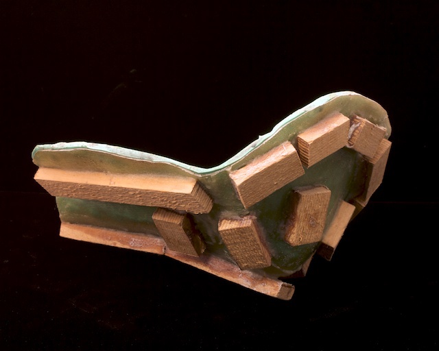
Mother Mold ConstructionThe fiberglass mother mold and wood stiffening and mounting members provide the necessary stiffness to support the silicone mold. The mold and mother mold are keyed together to index them for each layup. When cured, the part can be pulled from the mother mold with the silicone mold still attached followed by peeling the silicone mold away from the part.
Final Part - Underside ViewThe underside of the final part with attachments. The top (red) finish coats have been applied to opposite surface and this surface will now receive finish material.
Finished Part - Top (mold face) ViewTop surface of part with lacquer finish awaiting hand rub out. The shape of the mold introduces a ridge along the outside edge of the part to assist with final trim to size. The Saumrai luminaire for which this part was made for can be seen at my website.
Non-comforming die press work
An interesting sheet metal forming process common to the jewelry trade is used to make formed metal parts. A simple hydraulic press is used to press a hard die into a medium durometer (flexible) urethane material with the sheet work piece sandwiched in between. Since there is no mirror image die used in the process, it is referred to as a non-comforming die procedure. A rigid containment vessel is key to the procedure. Since the flexible urethane in the containment vessel is relatively non-compressible, when the assembly is put under pressure, the utethane flows into the die cavity taking the metal along with it. Depending upon the particular metal in use, a series of annealing steps may be required to complete the form without cracking it due to work-hardening.
An interesting sheet metal forming process common to the jewelry trade is used to make formed metal parts. A simple hydraulic press is used to press a hard die into a medium durometer (flexible) urethane material with the sheet work piece sandwiched in between. Since there is no mirror image die used in the process, it is referred to as a non-comforming die procedure. A rigid containment vessel is key to the procedure. Since the flexible urethane in the containment vessel is relatively non-compressible, when the assembly is put under pressure, the utethane flows into the die cavity taking the metal along with it. Depending upon the particular metal in use, a series of annealing steps may be required to complete the form without cracking it due to work-hardening.

Tooling for die work At left is the medium durometer urethane containment structure. A right is the forming die made of rigid urethane. And at bottom is an assembly made up of parts taken from this process.

Hydraulic PressA shop-built press based upon a popular design used by jewelers. A pneumatic cylinder from the shop part collection serves the return stroke function typically provided by springs in this design.
I originally intended the cylinder to also provide a faster coarse movement on the up stroke but limitations in the hydraulic bottle jack design seem to cause issues with the function.
I originally intended the cylinder to also provide a faster coarse movement on the up stroke but limitations in the hydraulic bottle jack design seem to cause issues with the function.
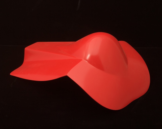
A Completed Part AssemblyTop surface of assembly with lacquer finish and aluminum fittings. This part was made for a series of luminaire designs including one entitled Palomar.
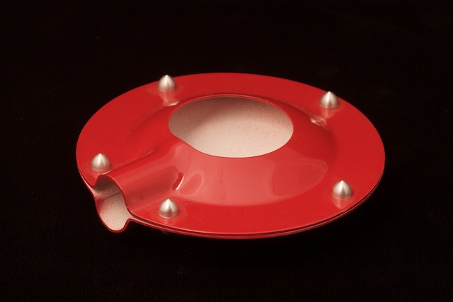
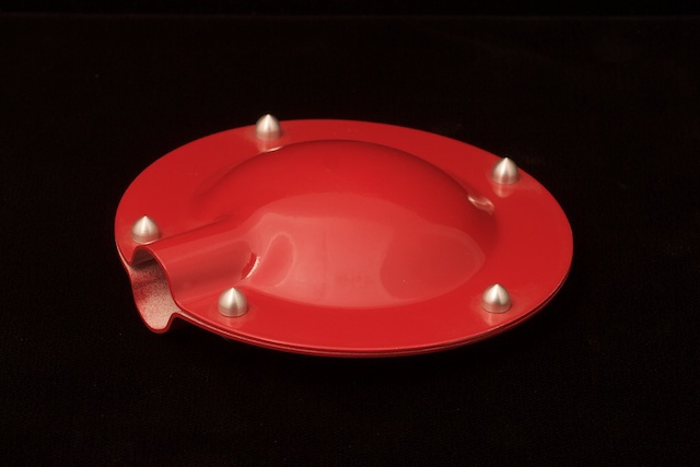
Completed Part Assembly - Bottom View
The bottom of this shade element for a luminaire design has been machined for an opening in a secondary operation using a copy of the original die as the fixture for use in the milling machine.
The bottom of this shade element for a luminaire design has been machined for an opening in a secondary operation using a copy of the original die as the fixture for use in the milling machine.
Milling Machine Operations
Standard machine shop techniques in use include working with a milling machine. The shop relies upon a Swiss-made Aciera universal mill. Unlike the typical Bridgeport pattern mills common in the U.S.A., this machine features a layout typical of machines produced in Europe. The basic machine is a horizontal mill with drive motor in the base and a two axis tilt table. A pair of accessory heads add low-speed, base-drive vertical milling and separate top-drive, high-speed vertical to the machine's capabilities.
Standard machine shop techniques in use include working with a milling machine. The shop relies upon a Swiss-made Aciera universal mill. Unlike the typical Bridgeport pattern mills common in the U.S.A., this machine features a layout typical of machines produced in Europe. The basic machine is a horizontal mill with drive motor in the base and a two axis tilt table. A pair of accessory heads add low-speed, base-drive vertical milling and separate top-drive, high-speed vertical to the machine's capabilities.

I stand here next to the Aciera F3 - a wonder of Swiss engineering designed with a small working envelope ideal for the typical range of work I do. It has a different operator layout from the typical Bridgeport style milling machines. The milling head moves to implement the Y axis with X and Z controlled through the table. A feature I really like is the built-in X-axis drive that shares the main spindle drive motor in the base of the machine. The head shown here has its own drive motor and is designed for higher speed operations. In addition to a second low speed vertical head driven by the base motor, there is a horizontal milling axis - also driven by the base motor. Along with the typical head tilting action, the universal style machines like the Aciera have dual axis tilts at the table as well.


